Organic light-emitting display with solar cell

a solar cell and light-emitting display technology, applied in the direction of thermoelectric device junction materials, electrical apparatus, semiconductor devices, etc., can solve the problems of limited emission efficiency and energy waste of conventional organic light-emitting display, and achieve the effect of saving the whole and avoiding energy was

Inactive Publication Date: 2014-08-14
WINTEK CHINA TECH LTD +1
View PDF9 Cites 16 Cited by
  • Summary
  • Abstract
  • Description
  • Claims
  • Application Information

AI Technical Summary

Benefits of technology

[0007]It is an advantage of the present invention that at least one solar cell unit is disposed between the organic light-emitting units that the solar cell unit can be used to absorb the light not emitting out the display when it displaying images. The solar cell unit can generate current so as to avoid energy waste and further save the whole energy consummation of the organic light-emitting display.
[0008]These and other objectives of the present invention will no doubt become obvious to those of ordinary skill in the art after reading the following detailed description of the preferred embodiment that is illustrated in the various figures and drawings.

Problems solved by technology

Accordingly, the emission efficiency of a conventional organic light-emitting display is limited.
On the other hand, that a part of light cannot emit out the display panel because of total internal reflection also induces the issue of energy waste.

Method used


Image

  • Organic light-emitting display with solar cell
  • Organic light-emitting display with solar cell
  • Organic light-emitting display with solar cell

Examples


first embodiment

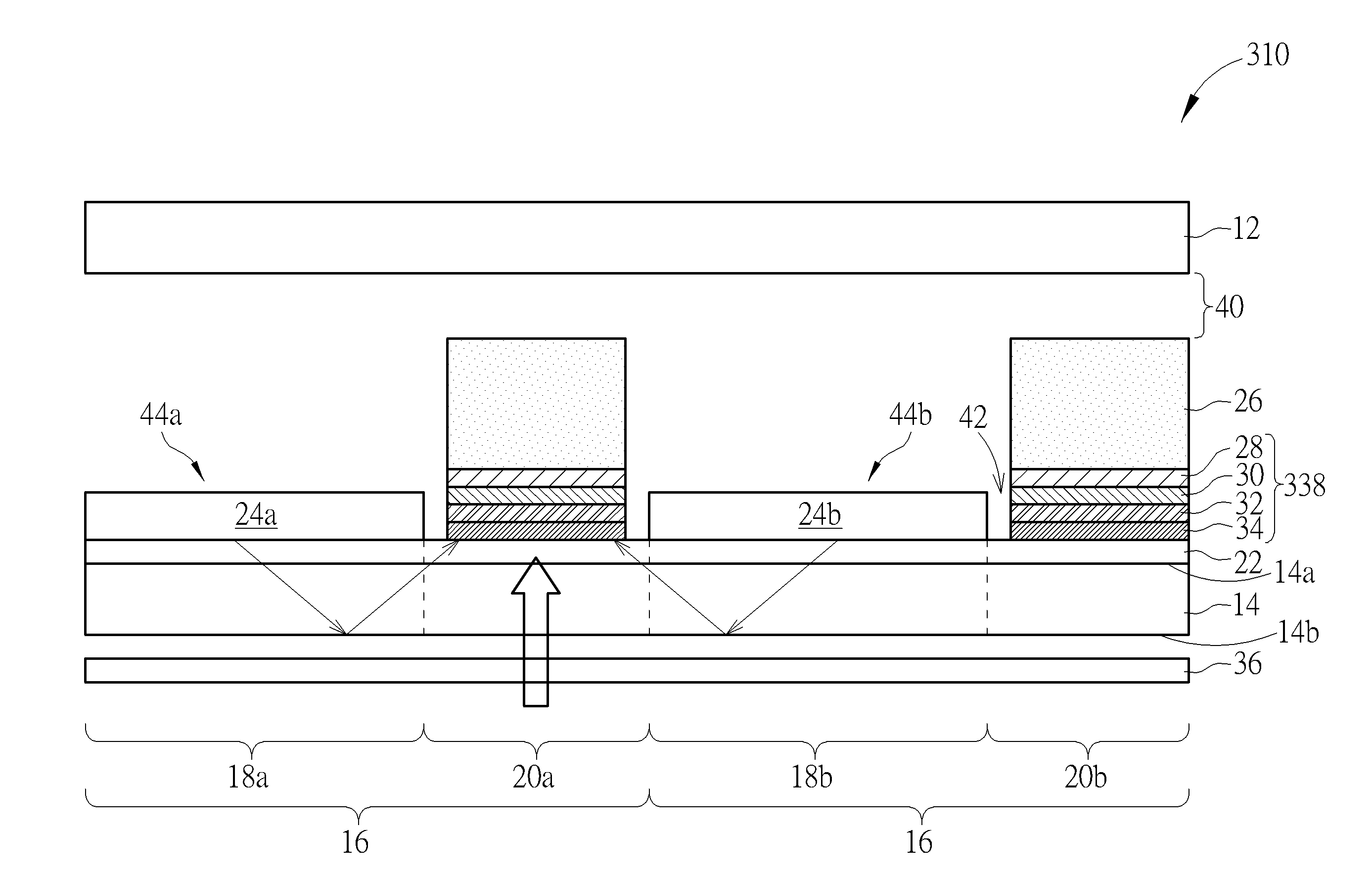
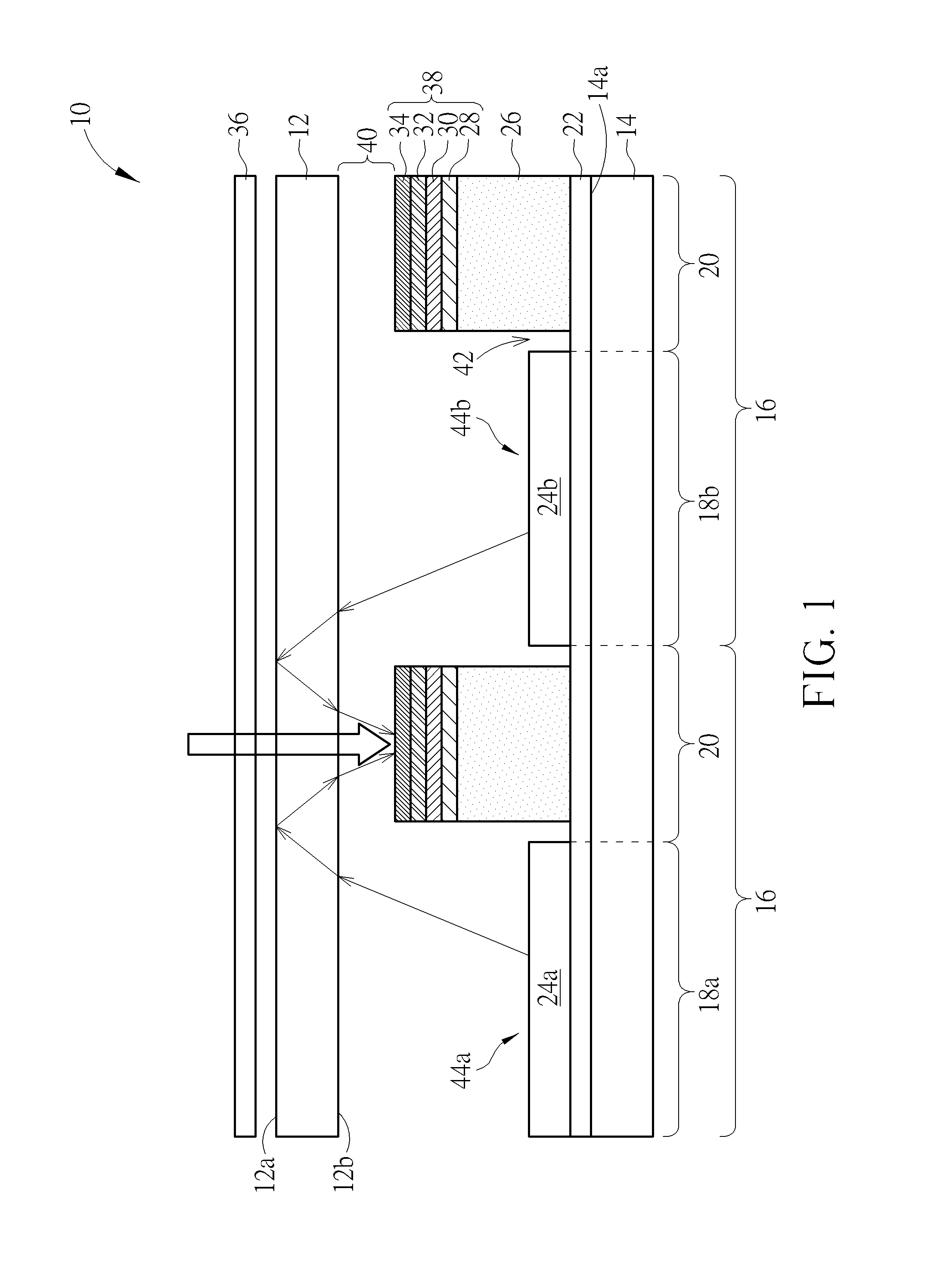
[0013]Referring to FIG. 1, FIG. 1 is a schematic sectional-view of an organic light-emitting display with solar cell according to the present invention. The organic light-emitting display 10 with solar cell of the present invention includes a first substrate 12 and a second substrate 14, wherein the second substrate 14 and the first substrate 12 are disposed oppositely. As shown in FIG. 1, the second substrate 14 is disposed at a bottom side of the first substrate 12 and the second substrate 14 has an inside surface 14a facing the bottom surface of the first substrate 12, which is the inside surface 12b of the first substrate 12. The second substrate 14 includes a plurality of pixels 16 defined thereon, wherein the pixels 16 are arranged as an array. The pixels 16 used herein may also refer to the sub-pixels used to produce any primary color lights or any other color lights for composing display images, but not limited thereto. Each pixel 16 includes an emission region (marked as 18...

second embodiment

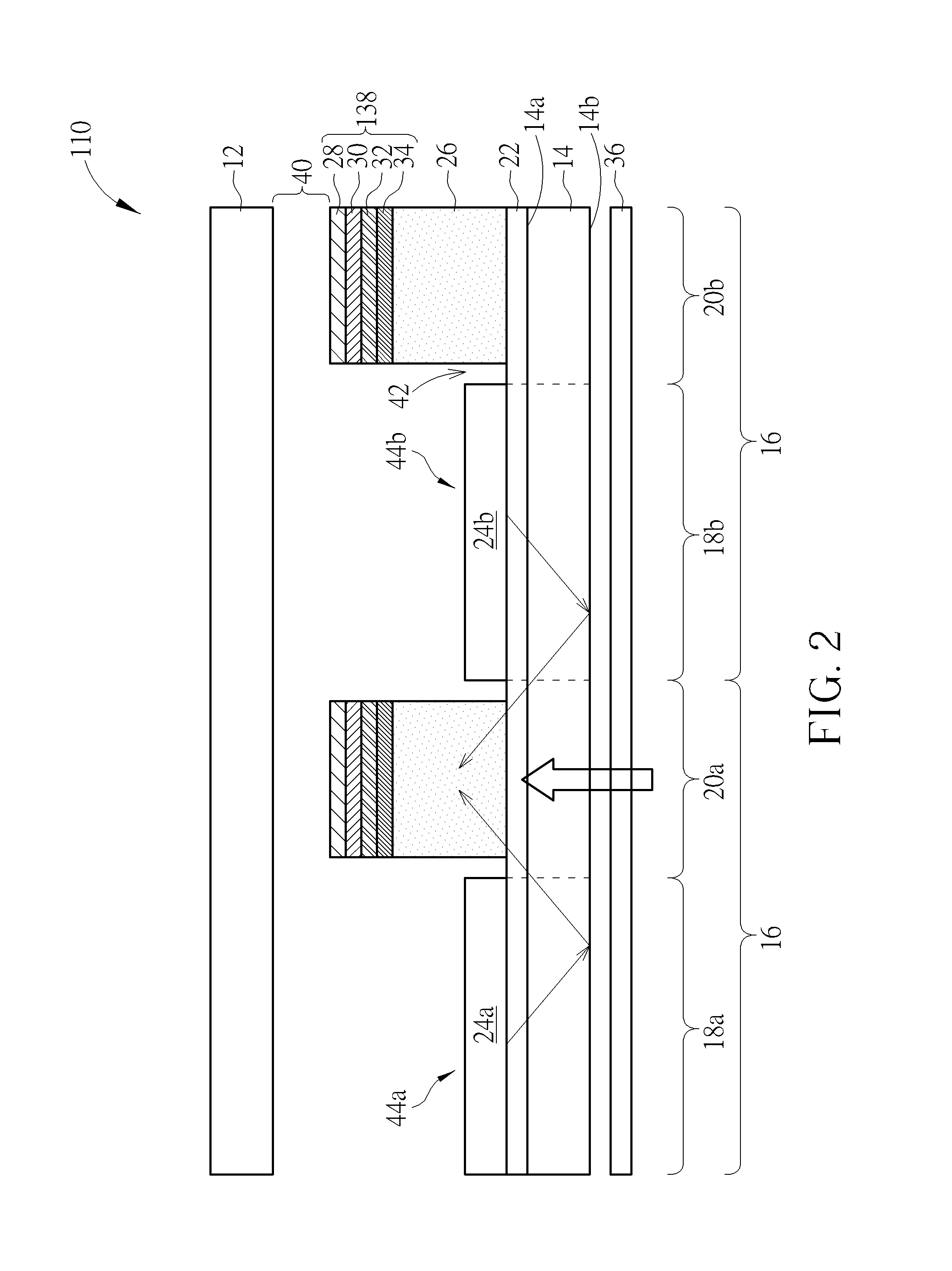
[0019]Referring to FIG. 2, FIG. 2 is a schematic sectional-view of an organic light-emitting display with solar cell according to the present invention. Different from the previous embodiment, the organic light-emitting display 110 of this embodiment is a bottom emission type active organic light-emitting display, thus the outside surface 14b of the second substrate 14 is the light emitting side of the organic light-emitting display 110 for displaying images. Furthermore, the arranging order of the multiple film layers of the solar cell units 138 of this embodiment is different from the previous embodiment. On the surface of the bank 26, the second electrode layer 34, the transport layer 32, the absorption layer 30 and the first electrode layer 28 are disposed in order from bottom to top, which means the second electrode layer 34, the transport layer 32, the absorption layer 30 and the first electrode layer 28 are disposed in order from a side near the second substrate 14 to a side ...


PUM


Abstract

An organic light-emitting display with a solar cell includes a first substrate, a second substrate, a plurality of organic light-emitting units, and at least one solar cell unit. The second substrate is disposed oppositely to the first substrate and has an inside surface facing the first substrate. The organic light-emitting units are arranged as an array on the inside surface of the second substrate. The second substrate has non-emission regions positioned between any two adjacent light-emitting units. The solar cell unit is disposed in one of the non-emission region for receiving the light generated by the solar cell units to produce current.

Description

BACKGROUND OF THE INVENTION[0001]1. Field of the Invention[0002]The present invention relates to an organic light-emitting display (OLED), and more particularly, to an organic light-emitting display with solar cell.[0003]2. Description of the Prior Art[0004]An organic light-emitting display adopts organic light-emitting materials in an active array display panel, which is controlled by the driving current to achieve the effect of different brightness. The organic light-emitting display has advantages such as power saving, low limitation of viewing angle, lower manufacturing cost, a shorter response time, a wider range of operated temperature and flexible miniaturization in accordance with the hardware. As a result, the organic light-emitting display has great development potential in a flat display device. However, most organic light-emitting materials have high refractive indices, resulted in that the critical angle of total internal reflection is very small for the light generated...

Claims


Application Information

Patent Timeline
Patent Type & Authority Applications(United States)
IPC IPC(8): H01L27/32
CPCH01L27/3227H01L27/3246H01L27/288H10K65/00H10K59/122
Inventor FANG, CHONG-YANGCHEN, PING-YENGKANG, HEN-TACHANG, CHIA-HSIUNG
Owner WINTEK CHINA TECH LTD
Why Eureka
Try Eureka