Poweline pulse position modulated three-phase transmitter apparatus and method

a three-phase transmitter and pulse position technology, applied in the field of pulse position modulation three-phase transmitter apparatus and method, can solve the problems of inability to control lighting levels, inability to do distribution and timing, and infrequently, and achieve the effect of reducing the cost of rewiring, increasing efficiency, and complex reconfiguring control

Inactive Publication Date: 2014-08-14
POWERLINE CONTROL SYST
View PDF5 Cites 10 Cited by
  • Summary
  • Abstract
  • Description
  • Claims
  • Application Information

AI Technical Summary

Benefits of technology

[0011]It is a purpose and advantage of the present invention to provide a method and apparatus for reliable transmission of digital data over the powerline in a three-phase power system by means of a pulse position modulated three-phase repeater apparatus and method utilizing an active repeating system.
[0012]It is a further purpose and advantage of the present invention to provide a method and apparatus for powerline pulse transmission wherein the voltage zero crossing is sensed and the communication signal pulse is transmitted and sensed in a receiver based on the signal position relative to either the zero crossing point or the position of one or more previous transmitted synchronization pulses.
[0013]It is a further purpose and advantage of the present invention to provide a method and apparatus by a powerline pulse position modulation transmission method for

Problems solved by technology

Normally, changes in the control of lighting levels, distribution and timing is not done, or done very infrequently because it is inconvenient or impossible to do so with conventional control systems.
Often in retrofit applications the wiring does not allow for controlling separate zones and/or lighting levels and the cost of rewiring is often prohibitive.
One problem relates to the connection and communication between the controller and the lighting or HVAC loads.
Most conventional connections are currently hard-wired, and trying to reconfigure the control for increased efficiency can be very complex and prohibitively expensive.
Another disadvantage of any hard-wired system is that it may be very costly to change the configuration if the use pattern changes.
Depending on how the different lighting zones are initially wired it may be impossible to match the old lighting zones to the new production zones thereby requiring all lights to be left on 24 hours a day using energy unnecessarily.
Also, conventional, radio frequency type connection systems are known, but they have proven difficult to implement because of a combination of high noise and high attenuation found in the industrial environment and the fact that the FCC requires low signal levels.
Low signal levels are subject to interference and the transmission and receiving circuitry for this type of

Method used


Image

  • Poweline pulse position modulated three-phase transmitter apparatus and method
  • Poweline pulse position modulated three-phase transmitter apparatus and method
  • Poweline pulse position modulated three-phase transmitter apparatus and method

Examples


Embodiment Construction

[0039]The purpose of the powerline pulse position modulated communication transmitter apparatus of this invention as shown in FIGS. 1-20 is to enable the communication of digital data from one device to another by means of the powerline to which both devices are connected. A further purpose is to enable communication to control lighting or other electrical loads in one or more rooms of a building.

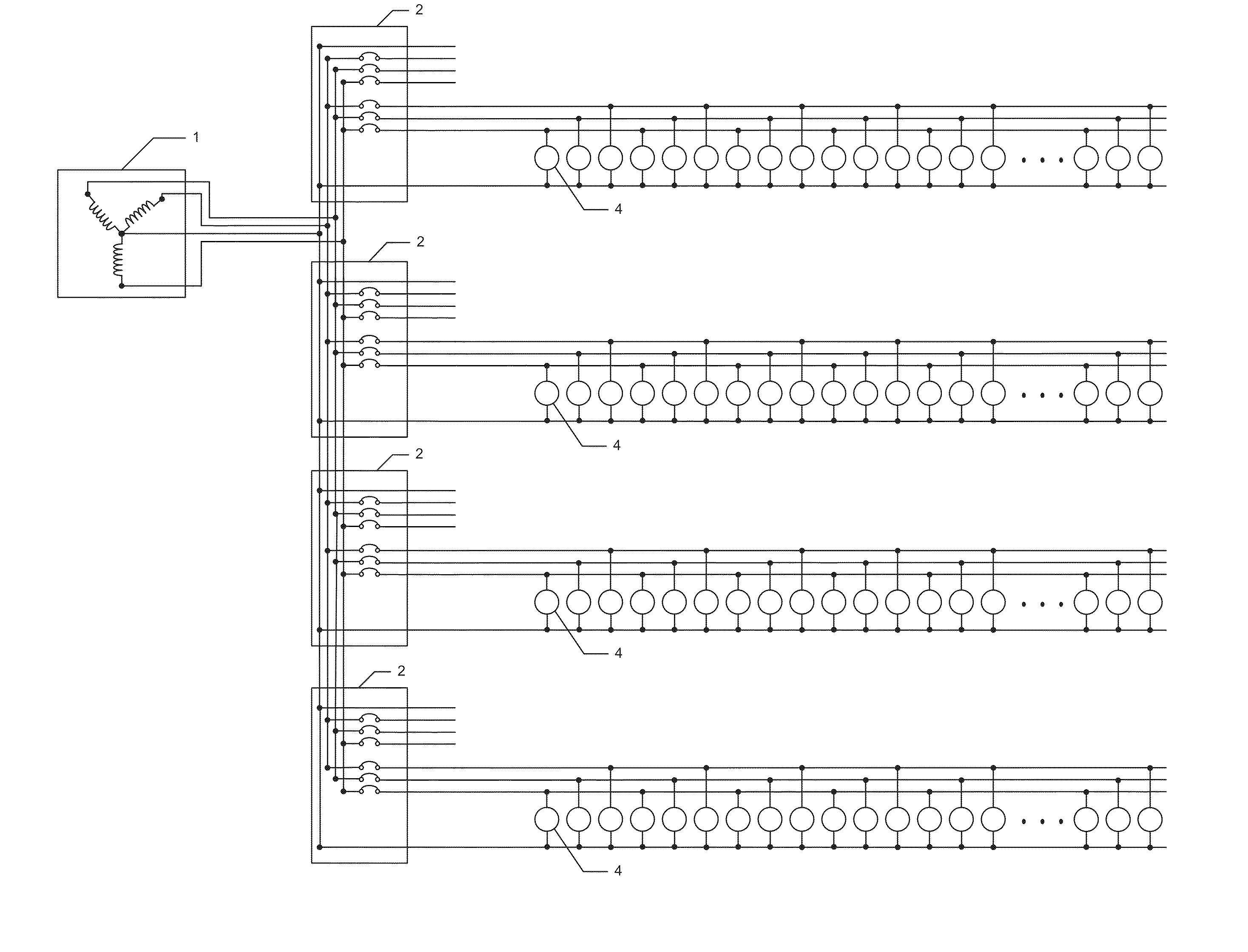
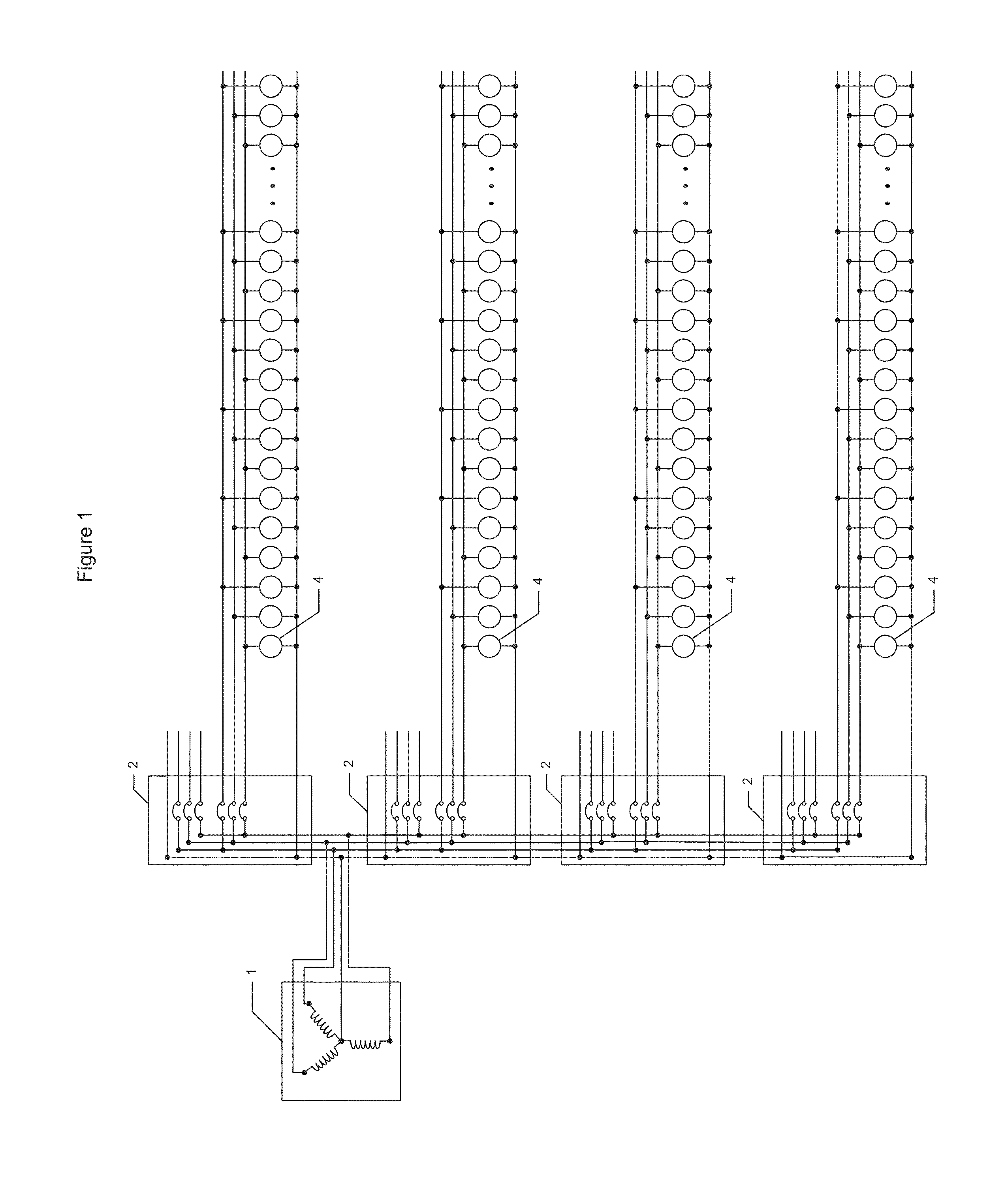
[0040]FIG. 1 is a Block Diagram of a Typical Lighting System without Controls

[0041]FIG. 1 is a schematic diagram of a typical industrial lighting system with no controls installed. Item 1 represents a three-phase transformer. This transformer is a Y type transformer. Item 2 of which there are four shown in this diagram represent circuit breaker panels. Each panel could be a 200 A or 400 A three-phase panel supplying 277V power. Reference number 4 in this diagram represents lighting fixtures which are dispersed throughout the building attached between neutral and one of the three phases A, B...


PUM


Abstract

An electrical control system consisting of two or more electrical transmitting devices each capable of transmitting synchronized messages consisting of electrical pulses to devices connected to one or more of the three phases of the AC power lines in a typical three phase power system. The synchronized transmitters are each connected to neutral and to one or more of the three phases, A, B, and C, or across two of the phases, of different circuit breaker panels in a typical three phase power system, and are capable of transmitting messages to one or more of the three phases. The transmissions from the two or more transmitters are synchronized such that the transmitted pulses from each transmitter are transmitted at the same time to produce a message that can be received correctly at any receiving device connected to any of the connected circuit breaker panels.

Description

FIELD OF THE INVENTION[0001]This invention is directed to an apparatus which enables the transmission and reception of digital communication from and to one or more devices wherein each of the devices is connected to at least the one of the phases of a three-phase power system and use the same three-phase power system as a physical channel for the digital intercommunication.BACKGROUND OF THE INVENTION[0002]Many electrical devices may be more conveniently used if they can be remotely controlled. For example, in an industrial application, such devices are mostly HVAC and lighting loads. The HVAC and lighting loads may be remotely controlled for a number of different reasons. For energy conservation reasons, some lights may be controlled by a timer. In other cases, different lighting intensity and different lighting distribution may be desirable in a single building zone, depending upon its use. Each application suggests a different lighting level and different lighting distribution an...

Claims


Application Information

Patent Timeline
IPC IPC(8): H02J3/00
CPCH02J3/00H05B37/0263H04B3/00H02J13/0024H04B3/542H04B3/58H04B14/026H04B2203/5416H04B2203/5466H02J13/00004H02J13/00009H02J2310/12H05B47/185H04B3/54
Inventor LESTER, MARSHALFIENBERG, RONLANE, PRESTON
Owner POWERLINE CONTROL SYST
Why Eureka
Try Eureka