Sc-fdma transmission device and transmission method

a transmission device and transmission method technology, applied in power management, wireless commuication services, coding, etc., can solve problems such as inter-symbol interference, and achieve good error rate performan

Active Publication Date: 2014-08-14
PANASONIC CORP
View PDF4 Cites 13 Cited by
  • Summary
  • Abstract
  • Description
  • Claims
  • Application Information

AI Technical Summary

Benefits of technology

[0030]According to the present invention, good error rate performances can be achieved in any propagation channel.

Problems solved by technology

This deteriorates unitarity (orthogonality) between the DFT matrix used in the transmitting DFT and the IDFT matrix used in the receiving IDFT, resulting in inter-symbol interference.

Method used


Image

  • Sc-fdma transmission device and transmission method
  • Sc-fdma transmission device and transmission method
  • Sc-fdma transmission device and transmission method

Examples


embodiment 1

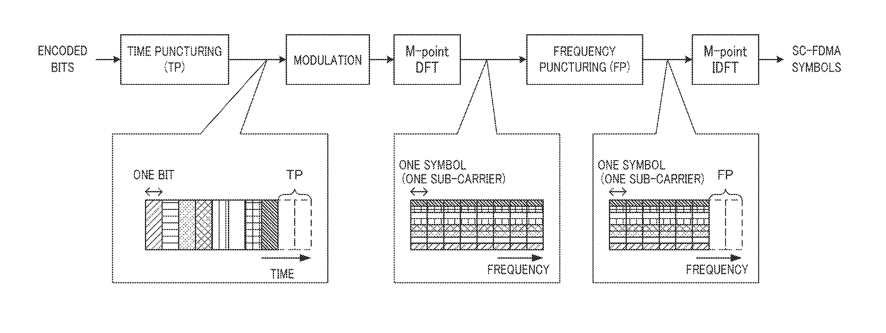
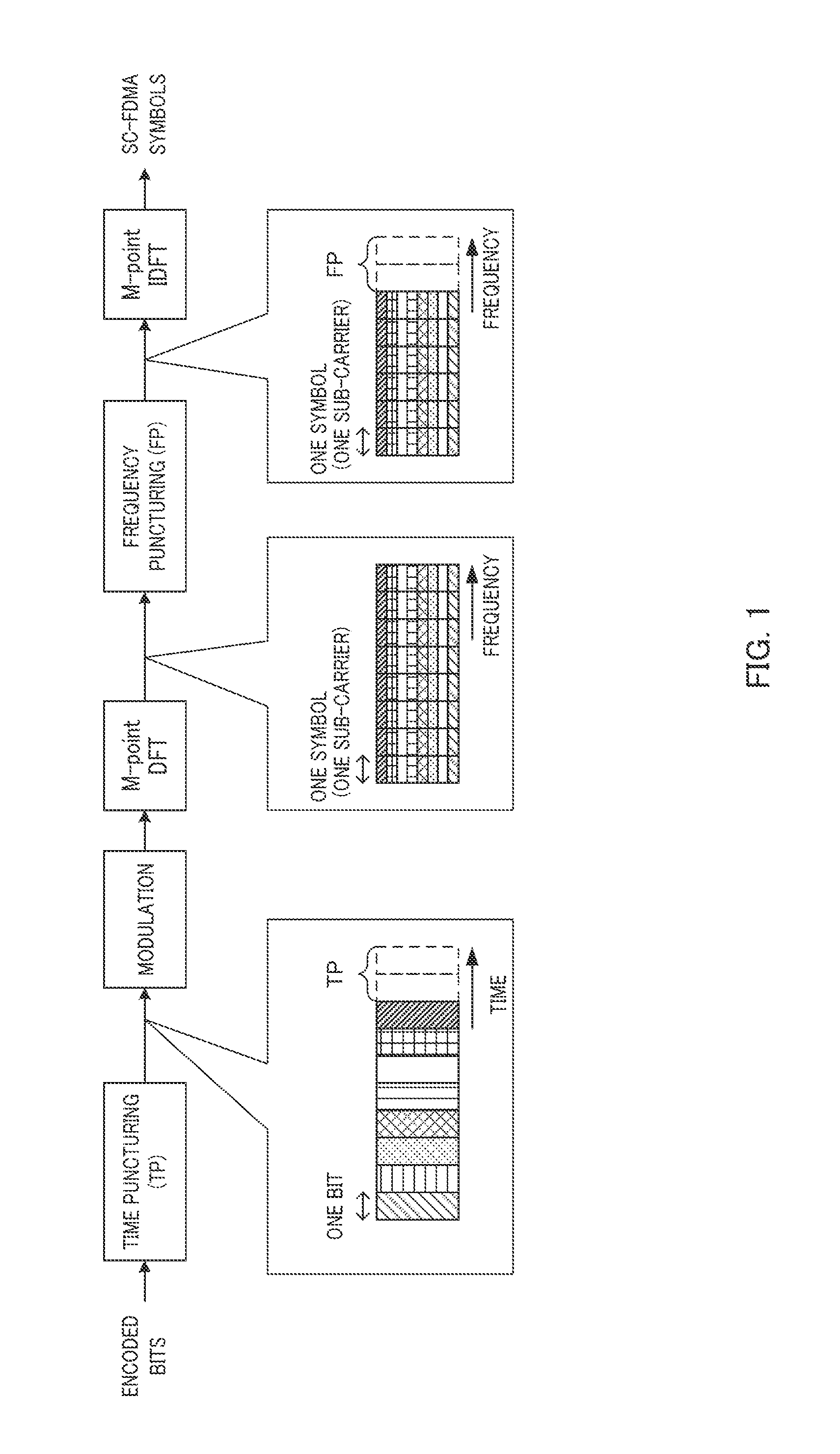
[0053]FIG. 5 illustrates major components of transmission apparatus 100 according to the present embodiment. Transmission apparatus 100 shown in FIG. 5 performs the time puncturing and the frequency puncturing. In transmission apparatus 100, determination section 151 determines, according to puncturing determination rules, a ratio between the amount of time puncturing and the amount of frequency puncturing in the total amount of puncturing corresponding to components of encoded data that are punctured in the time puncturing and the frequency puncturing; setting section 152 sets the amount of time puncturing and the amount of frequency puncturing based on the above-mentioned ratio; time puncturing section 102 performs the time puncturing on the encoded data according to the amount of time puncturing; and frequency puncturing section 105 performs the frequency puncturing on the encoded data after the time puncturing according to the amount of frequency puncturing. In this process, acc...

embodiment 2

[0150]A description will also be provided for the case where the frequency puncturing rate is set depending on the number of clusters that are allocated to a transmission apparatus (the number of allocated clusters, hereinafter denoted by NC), according to the present embodiment.

[0151]Reception apparatus 200 (FIG. 7) performs demodulation processing on clusters transmitted from transmission apparatus 100 (FIG. 6) based on channel estimation values derived by means of DMRSs, for example. These DMRSs are mapped to frequency bands allocated to the clusters. Moreover, reception apparatus 200 estimates a channel estimation value (for example, SINR) for each frequency band (sub-carrier) by using three sub-carriers, i.e., the channel estimation target sub-carrier and two nearest sub-carriers on both sides of the channel estimation target sub-carrier, for example. When the channel of a sub-carrier located at the outer end of a cluster is to be estimated, reception apparatus 200 cannot use o...

embodiment 3

[0167]A description will also be provided for the case where the frequency puncturing rate is set depending on the number of antennas used by a reception apparatus according to the present embodiment.

[0168]FIG. 18A illustrates the channel gain when reception apparatus 200 (FIG. 7) receives a signal from transmission apparatus 100 (FIG. 6) via one receiving antenna (i.e., single-antenna reception). In contrast, FIG. 18B illustrates the channel gain after antenna combining when reception apparatus 200 receives a signal from transmission apparatus 100 via a plurality of receiving antennas (the number of receiving antennas 2) (i.e., multi-antenna reception, or antenna-diversity reception).

[0169]As can be seen by comparing FIG. 18A with FIG. 18B, the channel gain after antenna combining obtained by multi-antenna reception shown in FIG. 18B results in a smaller number of dropped sub-carriers which may cause ISI than the channel gain obtained by single-antenna reception shown in FIG. 18A. ...


PUM


Abstract

An SC-FDMA transmission device capable of achieving excellent error rate characteristics on any propagation channel, wherein a determination unit (151) determines the ratio of the frequency puncturing amount to the time puncturing amount in the total puncturing amount on the basis of a puncturing determination rule, and a setting unit (152) sets the time puncturing amount and the frequency puncturing amount on the basis of this ratio. Here, in the puncturing determination rule, the ratio is determined from the MCS of the encoded data, the number of resources allocated to the encoded data, and the delay spread of the propagation channel between a receiving device and the transmission device (100).

Description

TECHNICAL FIELD[0001]The present invention relates to a transmission apparatus and a transmission method.BACKGROUND ART[0002]3GPP LTE (3rd Generation Partnership Project Long Term Evolution) employs SC-FDMA (Single Carrier-Frequency Division Multiple Access) as its uplink access scheme. SC-FDMA features a low PAPR (Peak to Average Power Ratio) achieved by the single-carrier scheme of SC-FDMA, flexible allocation of data to sub-carrier frequencies, resilience to multipath interference in frequency-domain signal processing on the receiving side, and the like.[0003]In SC-FDMA, on the transmitting side, SC-FDMA signals are generated, for example, by converting time-domain symbols into frequency components by a DFT (Discrete Fourier Transform), mapping the frequency components to respective different sub-carriers, then, converting the mapped frequency components back into time-domain waveform by an IDFT (Inverse Discrete Fourier Transform), and adding a CP (Cyclic Prefix) to the time-dom...

Claims


Application Information

Patent Timeline
Patent Type & Authority Applications(United States)
IPC IPC(8): H04W52/54
CPCH04W52/54H04L27/2636H04L1/0068H03M13/2957H03M13/6362H03M13/353H03M13/6525
Inventor KIMURA, RYOHEIOIZUMI, TORUOGAWA, YOSHIHIKOIMAMURA, DAICHIADACHI, FUMIYUKIYAMAMOTO, TETSUYA
Owner PANASONIC CORP
Why Eureka
Try Eureka