
Sub-Millinewton Capacitive Mems Force Sensor for Mechanical Testing on a Microscope

a capacitive mems force sensor and microscope technology, applied in the direction of force/torque/work measurement apparatus, measurement devices, instruments, etc., can solve the problems of high cost, limited number of applications for which the sensor can be used, and inconvenient configuration

Active Publication Date: 2014-08-21
FEMTOTOOLS
View PDF8 Cites 4 Cited by
  • Summary
  • Abstract
  • Description
  • Claims
  • Application Information

AI Technical Summary

Benefits of technology

The present invention is a capacitive micro force sensor that solves the problem of prior art force sensors being unable to measure in-plane mechanical testing (a- and b-direction) and vertical testing (c-direction) of samples. The sensor has a probe that overhanges the substrate on one side, allowing for measurements in both horizontal and vertical directions. The sensor design also allows for easy calibration and interpretation of measurement data.

Problems solved by technology

However, multi-axis force sensors are difficult to calibrate at the sub-Millinewton range and therefore highly expensive.
Prior art sensor designs described in [1]-[9] do not feature a probe (2) which is overhanging the substrate (7) on two sides (8,9), limiting the number of application for which the sensor can be used due to geometrical limitations.
Also, this configuration is not suitable since the substrate touches the microscope lens 12 making the measurement impossible.

Method used


Image

  • Sub-Millinewton Capacitive Mems Force Sensor for Mechanical Testing on a Microscope
  • Sub-Millinewton Capacitive Mems Force Sensor for Mechanical Testing on a Microscope
  • Sub-Millinewton Capacitive Mems Force Sensor for Mechanical Testing on a Microscope

Examples


Embodiment Construction

[0012]For a more complete understanding of the present disclosure, and the advantages thereof, reference is now made to the following descriptions taken in conjunction with the accompanying drawings, in which:

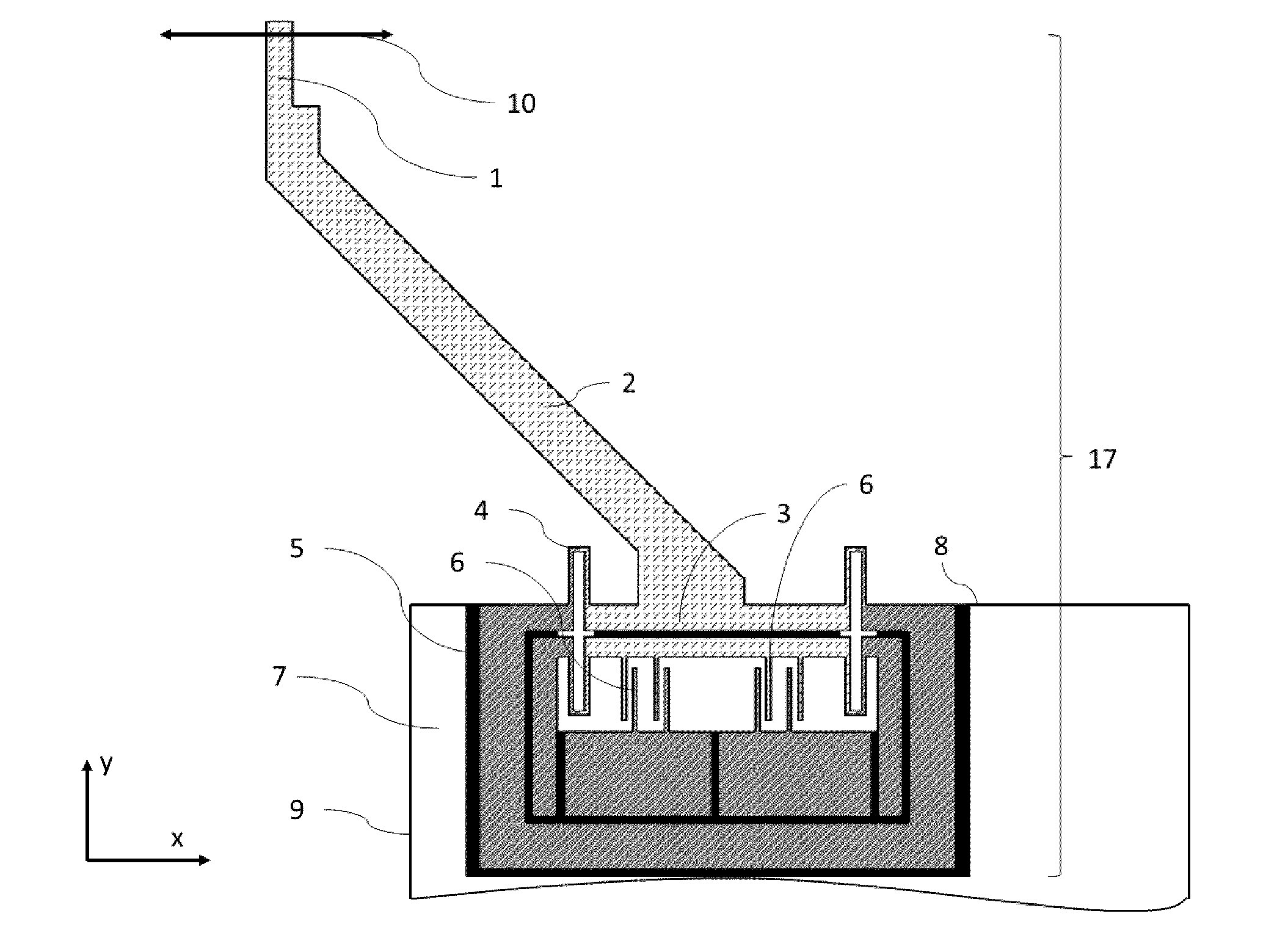
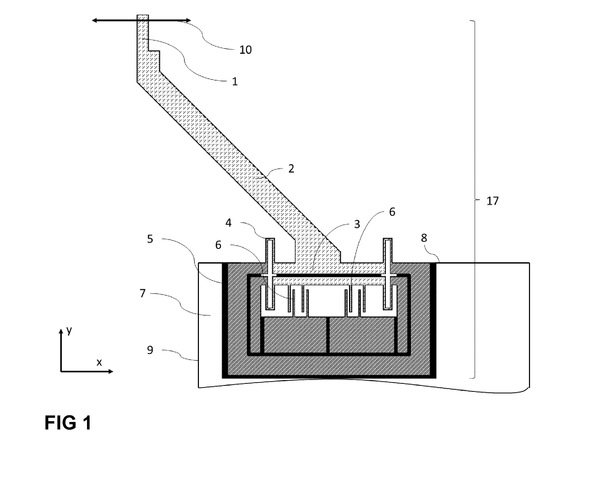
[0013]FIG. 1 depicts a capacitive MEMS sensor in a schematic view;

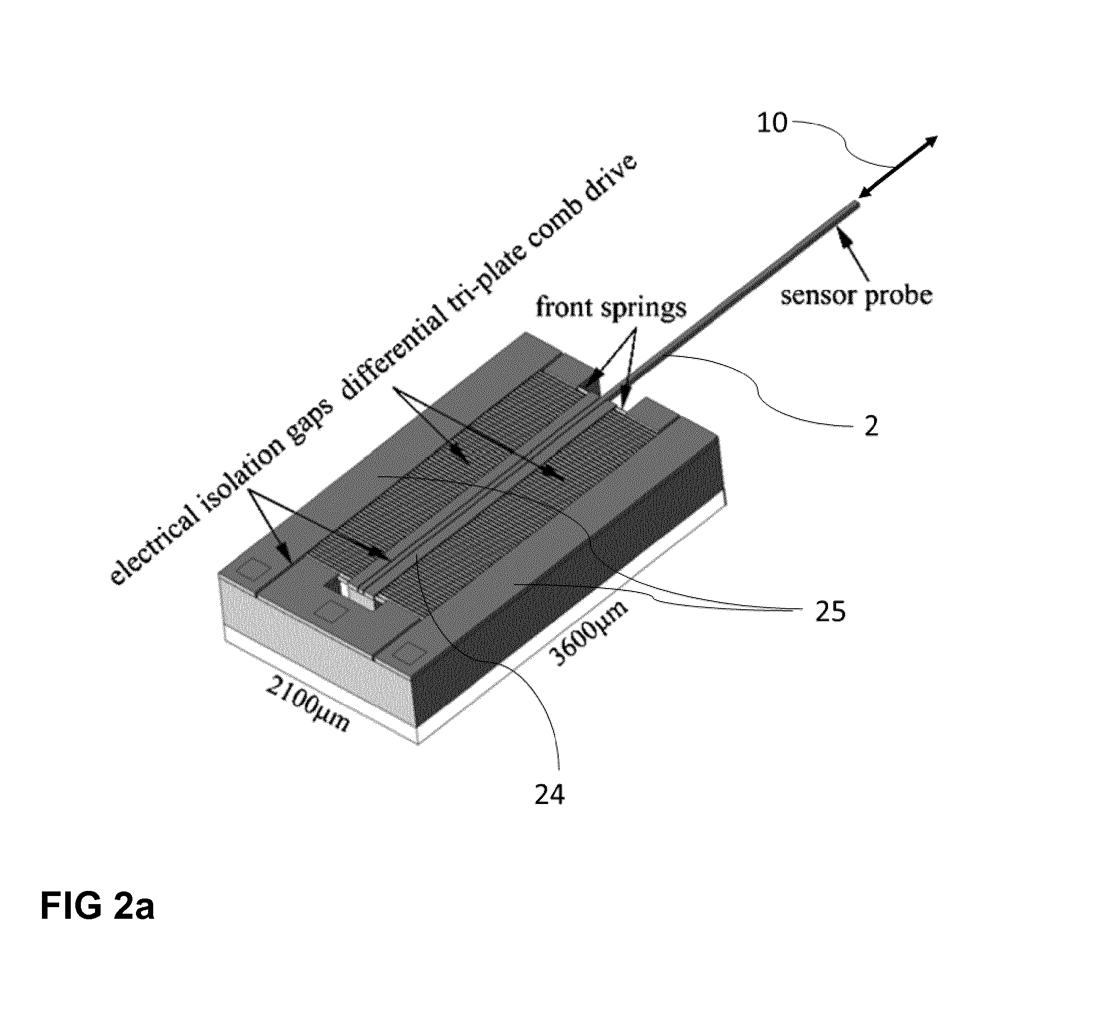
[0014]FIG. 2a depicts a depicts a prior art sensor by Sun Yu et al.;

[0015]FIG. 2b depicts a capacitive MEMS sensor with some geometrical indications;

[0016]FIG. 3 depicts the electrical and mechanical sensor buildup;

[0017]FIG. 4a depicts the mechanical testing using prior art sensors;

[0018]FIG. 4b depicts the mechanical testing using the sensor design according to the invention;

[0019]FIG. 5a depicts a prior art sensor;

[0020]FIG. 5b depicts an embodiment of the invention;

[0021]FIG. 5c depicts an alternative embodiment of the invention.

[0022]FIG. 1 shows a schematic view of the force sensor design. FIG. 3 shows the electrical and mechanical buildup. The basic working principle is the following: A force is applied to...


PUM


Abstract

Most mechanical tests (compression testing, tensile testing, flexure testing, shear testing) of samples in the sub-mm size scale are performed under the observation with an optical microscope or a scanning electron microscope. However, the following problems exist with prior art force sensors as e.g they cannot be used for in-plane mechanical testing (a- and b-direction) of a sample; they cannot be used for vertical testing (c-direction) of a sample. In order to overcome the before mentioned drawbacks the invention comprises the following basic working principle: A force is applied to the probe (2) at the probe tip (1) of the sensor. The force is transmitted by the sensor probe (2) to the movable body (3) of the sensor. The movable body is elastically suspended by four folded flexures (4), which transduce the force into a deflection dx. This deflection is measured by an array of capacitor electrodes, called capacitive comb drive (6).

Description

[0001]The present invention relates to a capacitive micro force sensor according to claim 1.BACKGROUND[0002]Multiple methods for measuring force from the nanonewton (10−9 N) to millinewton (10−3 N) range exist such as atomic force microscopes, microscales, piezoresistive cantilevers and capacitive force sensors. These systems have been successfully used in different application fields including material science, microsystem development, nanotechnology, biological research, medical research, thin film characterization and quality control of miniaturized systems. Using these sensors in combination with a precise positioning device such as a micromanipulator, allows building compression and tensile testing systems for mechanical testing at the microscale.[0003]Capacitance is a measure of the electrical charge between two conductors separated by an air gap. A load applied to the sensor causes a deflection. As the conductors are moved closer to or farther from one another, the air gap ch...

Claims


Application Information

Patent Timeline
IPC IPC(8): G01L1/14
CPCG01L1/148G01L5/0057G01L5/165
Inventor BEYELER, FELIXMUNTWYLER, SIMONDIETZE, WOLFGANG
Owner FEMTOTOOLS
Learn More