Engine and engine-operated working machine

a working machine and engine technology, applied in the direction of engine starters, muscle operated starters, non-automatic control, etc., can solve the problems of clutch housing wear, two-stroke engines can work for a long time, etc., to prevent the engine from stopping, suppress the increase in engine speed, and improve the startability

Active Publication Date: 2014-08-21
HITACHI KOKI CO LTD
View PDF6 Cites 14 Cited by
  • Summary
  • Abstract
  • Description
  • Claims
  • Application Information

AI Technical Summary

Benefits of technology

The patent describes a control system for engines that improves startability and prevents engine stopping due to fouling on the spark plug while suppressing engine speed increase during start-up. The control system uses an ignition timing control and detects the throttle opening and engine speed to automatically adjust ignition timing. The system also includes a pre-ignition prevention function and a warm-up control function to maintain engine state. The technical effects of the patent are improved startability, prevention of engine stopping, and efficient warm-up of the engine.

Problems solved by technology

Therefore, the two-stroke engines can work for a long time by fuel feeding.
However, when the brake is operated, a centrifugal clutch and a clutch housing slide on each other.
If this state continues for a long time, the centrifugal clutch generates heat, which causes the clutch housing to wear.

Method used


Image

  • Engine and engine-operated working machine
  • Engine and engine-operated working machine
  • Engine and engine-operated working machine

Examples


first embodiment

[0037]Hereinafter, embodiments of the present invention will be described with reference to the accompanying drawings. Throughout the drawings, identical portions are denoted by the same reference symbols, and the repeated description thereof will be omitted. In this specification, a front side, a rear side, an upper side, and a lower side will be described with reference to directions shown in the drawings.

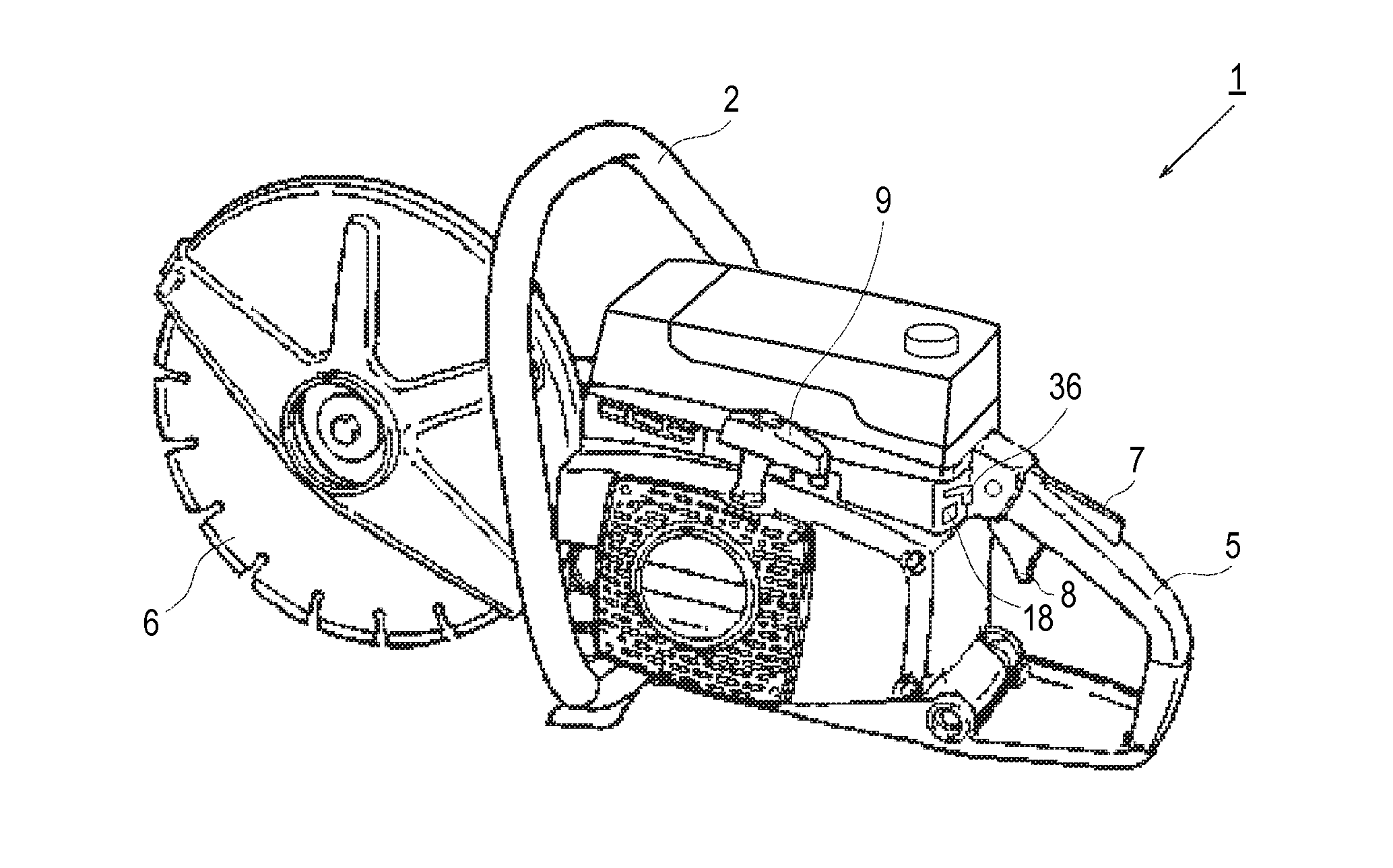
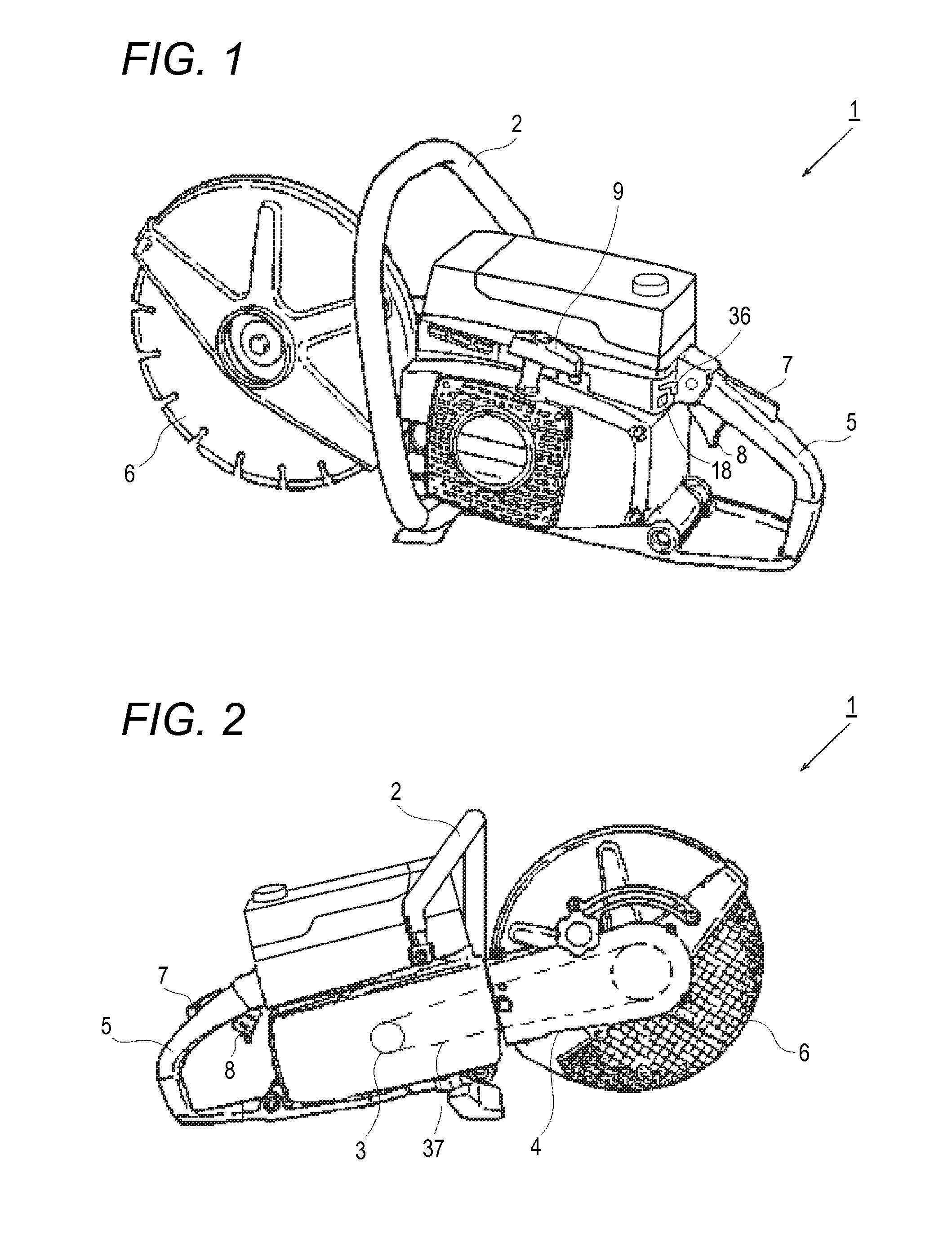
[0038]FIG. 1 is a perspective view illustrating an engine-operated working machine according to an embodiment of the present invention. A cutter 1 is an engine-operated working machine which includes a two-stroke engine (which will be described later) and revolves a front tool, that is, a rotary blade 6 by the power of the engine. A worker may hold a front handle 2 with the left hand and hold a rear handle 5 with the right hand. Then, the worker can operate a throttle trigger 8 while holding a locking lever 7 disposed at the rear handle 5, thereby adjusting the speed of the engin...

second embodiment

[0057]Next, operation timings of ignition timing control according to a second embodiment of the present invention will be described with reference to FIG. 11. In the second embodiment, in the case where the throttle-position detecting switch 26 is OFF, that is, in the case where the throttle trigger 8 is not held at the starting position, like in the ignition timing control according to the first embodiment, the CPU 44 transmits the ignition signal to the gate terminal 50 of the SCR 49 such that the ignition timing becomes, for example, 25 degrees BTDC, and ignition is performed at a predetermined ignition timing. On the other hand, in the case where the throttle-position detecting switch 26 is ON, that is, in the case where the throttle trigger 8 is held at the starting position, as shown in FIG. 11, if the engine speed exceeds a predetermined speed, for example, 3800 rpm, which is slightly lower than the speed when the centrifugal clutch 3 (see FIG. 2) becomes the engaged state, ...


PUM


Abstract

An engine is configured such that, during the starting of the engine, when it is being detected that throttle opening has been set at a starting position, if it is detected that the engine speed has exceeded a predetermined speed slightly lower than a speed when a centrifugal clutch becomes an engaged state, a control unit retards the ignition timing from a general angle to a first angle BTDC, and then advances the ignition timing to a second angle at predetermined intervals, and holds the ignition timing at the second angle for a predetermined time period, thereby preventing the engine from stopping due to fouling on the spark plug while suppressing the engine speed at the speed when the centrifugal clutch becomes the engaged state, or less.

Description

TECHNICAL FIELD[0001]The present invention relates to an engine and an engine-operated working machine such as a cutter, a chainsaw, or a bush cutter which uses the engine as a power source to drive an edge tool.BACKGROUND ART[0002]Small engines, particularly, two-stroke engines have been widely used as power sources in small working machines such as cutters, chainsaws, and bush cutters. The two-stroke engines are small and light and can obtain high power output. Therefore, the two-stroke engines can work for a long time by fuel feeding. As one of methods of improving the startability of those engines, there is known a method of opening a throttle valve of a carburetor from an almost fully closed position (hereinafter, referred to as an idle position) by a predetermined amount, thereby increasing an amount of intake air during starting.[0003]In a case of using this method, for example, if the throttle valve is fully opened for starting, the startability of a corresponding engine is ...

Claims


Application Information

Patent Timeline
IPC IPC(8): F02P5/02
CPCF02P5/02B27B17/083F02N1/005F02N3/02F02P5/1506F02P11/00F02D35/0053F02D2200/0404F02D2200/101F02D2400/04F02D2400/06F02N2250/06Y02T10/40
Inventor MEZAKI, AKIRAISHIDA, SHIGETOSHI
Owner HITACHI KOKI CO LTD
Why Eureka
Try Eureka