Induction Heating Augmentation for Thermal Curing

a technology of thermal curing and induction heating, which is applied in the field of thermoset composite parts fabrication, can solve the problems of shortening the curing thermal cycle, needing additional autoclaves or ovens, and reducing production throughput, so as to reduce the curing cycle time, increase the mass or thermal insulation characteristics, and facilitate installation

Active Publication Date: 2014-08-21
THE BOEING CO
View PDF2 Cites 16 Cited by
  • Summary
  • Abstract
  • Description
  • Claims
  • Application Information

AI Technical Summary

Benefits of technology

[0006]The disclosed embodiments provide a method and apparatus for augmenting thermal curing equipment such as autoclaves and ovens, in order to reduce cure cycle times and achieve precisely controlled curing of the thermoset composite parts. Thermal augmentation is achieved by strategic placement of inductive heating blankets in areas of the parts or their associated tooling that are normally slow-to-heat because of their higher mass or thermal insulation characteristics. The heating blankets employ inductive heating to achieve even, precisely controlled heating of the slow-to-heat part areas. The inductive heating blanket is easily installed and provides flexibility in production environments to achieve heating augmentation of selected part areas, regardless of the size or complexity of the part, and variations in mass or thermal insulation characteristics from part-to-part. The augmented heating of slow-to-heat areas of the parts accelerates heating of these areas, thereby shortening the curing thermal cycle. Although the disclosed embodiments may be used in connection with reducing cure cycles for thermoset parts, they may also be employed to heat other types of composites, such as thermoplastic parts, to a desired temperature during production processes.
[0008]According to a further embodiment, a method is provided of reducing the thermal cycle time required for heating a composite part in a heating chamber. The method comprises placing a heating blanket in proximity to an area of the composite part that is slow-to-heat, and inductively heating the area of the composite part that is slow-to-heat using the heating blanket. Placing a heating blanket in proximity to an area of the composite part includes placing the heating blanket against a tool that contacts the composite part. Inductively heating the area of the composite part is performed by inductively heating a susceptor sleeve in response to a magnetic field, reducing the inductive heating of the susceptor sleeve when the susceptor sleeve becomes non-magnetic upon reaching a Curie temperature of the susceptor sleeve, applying alternating current to a conductor having the susceptor sleeve mounted thereto, the susceptor sleeve being formed of magnetic material having the Curie temperature, and generating a magnetic field along the length of the susceptor sleeve in response to the alternating current.

Problems solved by technology

These extended cure cycle times reduce production throughput and may result in the need for additional autoclaves or ovens to meet higher production schedules.
The augmented heating of slow-to-heat areas of the parts accelerates heating of these areas, thereby shortening the curing thermal cycle.

Method used


Image

  • Induction Heating Augmentation for Thermal Curing
  • Induction Heating Augmentation for Thermal Curing
  • Induction Heating Augmentation for Thermal Curing

Examples


Embodiment Construction

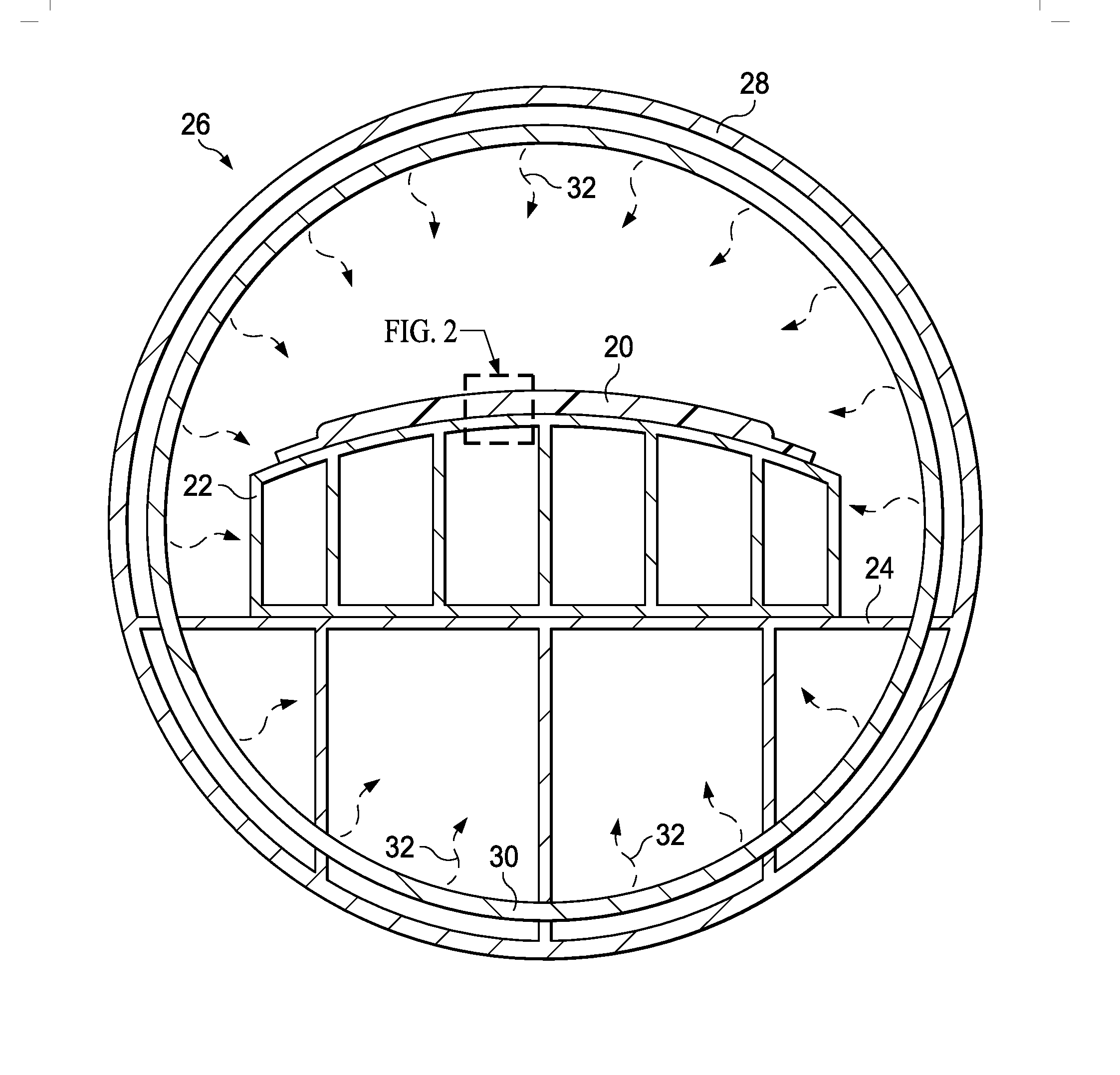
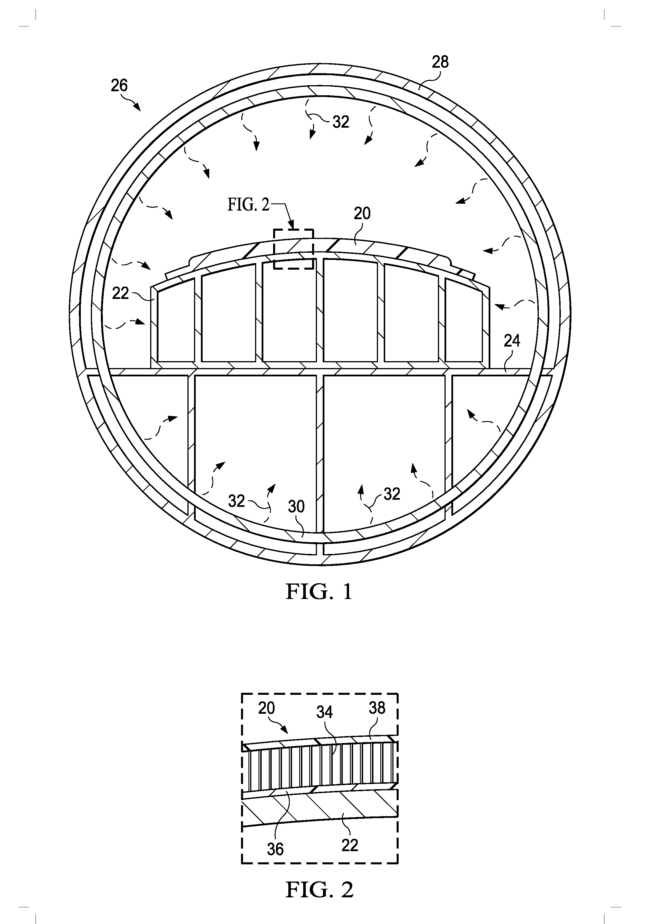
[0026]Referring first to FIGS. 1 and 2, an uncured, thermoset resin composite part 20 may be placed on a cure tool 22 for curing in an autoclave 26. The assembly of the composite part 20 and cure tool 20 are supported on a cure rack 24 inside a pressure vessel 28 forming part of the autoclave 26. As shown in FIG. 2, the composite part 20 may comprise, for example and without limitation, a sandwich panel comprising a honeycomb core 34 sandwiched between inner and outer facesheets 36, 38, respectively. Each of inner and outer facesheets 36, 38 may comprise multiple laminated plies (not shown) of a fiber reinforced thermosetting resin, such as carbon fiber epoxy. A wide range of other constructions and geometries are possible for the thermoset composite part 20.

[0027]The composite part 20 is cured by subjecting it to a combination of heat and pressure within the autoclave 26, according to a predetermined cure schedule specifying applied pressures, temperatures and durations for which t...


PUM

PropertyMeasurementUnit
frequenciesaaaaaaaaaa
areaaaaaaaaaaa

Abstract

The thermal cycle time for curing a thermoset composite part in an autoclave is reduced by placing a heating blanket in proximity to an area of the composite part that is slow-to-heat, and inductively heating the area of the composite part that is slow-to-heat using the heating blanket.

Description

BACKGROUND INFORMATION[0001]1. Field:[0002]The present disclosure generally relates to the fabrication of thermoset composite parts, and deals more particularly with techniques for thermal curing of the parts.[0003]2. Background:[0004]Thermal curing of thermoset composite parts may be carried out in an oven or an autoclave where a heat source such as resistive heating elements, supplies heat to the part through a combination of conduction, convection and radiation. Full curing requires that all areas of the part being heated to the necessary cure temperature for a prescribed period of time. Where parts have areas of different masses or thermal insulation characteristics, typical of larger, more complex parts, extended cycle times may be required to carry out full curing because the part areas having a higher mass or thermal insulation characteristic are slower to heat up to the required cure temperature. These extended cure cycle times reduce production throughput and may result in ...

Claims


Application Information

Patent Timeline
Patent Type & Authority Applications(United States)
IPC IPC(8): H05B1/00
CPCH05B1/00B29C35/0227B29C35/0805B29C2035/0811B29C2035/0816
Inventor MATSEN, MARC ROLLOMILLER, ROBERT JAMESSMITH, BRIAN W.BUTLER, GEOFFREY ALLENNELSON, KARL MARIUS
Owner THE BOEING CO
Why Eureka
Try Eureka