Fast-Settling Capacitive-Coupled Amplifiers

Active Publication Date: 2014-08-21
MAXIM INTEGRATED PROD INC
View PDF0 Cites 23 Cited by
  • Summary
  • Abstract
  • Description
  • Claims
  • Application Information

AI Technical Summary

Problems solved by technology

This input CM supply current often has an undesired influence on the system to be measured.
Therefore these amplifiers are not fit for fast-settling signal transfer.
Therefore an uncontrol

Method used


Image

  • Fast-Settling Capacitive-Coupled Amplifiers
  • Fast-Settling Capacitive-Coupled Amplifiers
  • Fast-Settling Capacitive-Coupled Amplifiers

Examples


Embodiment Construction

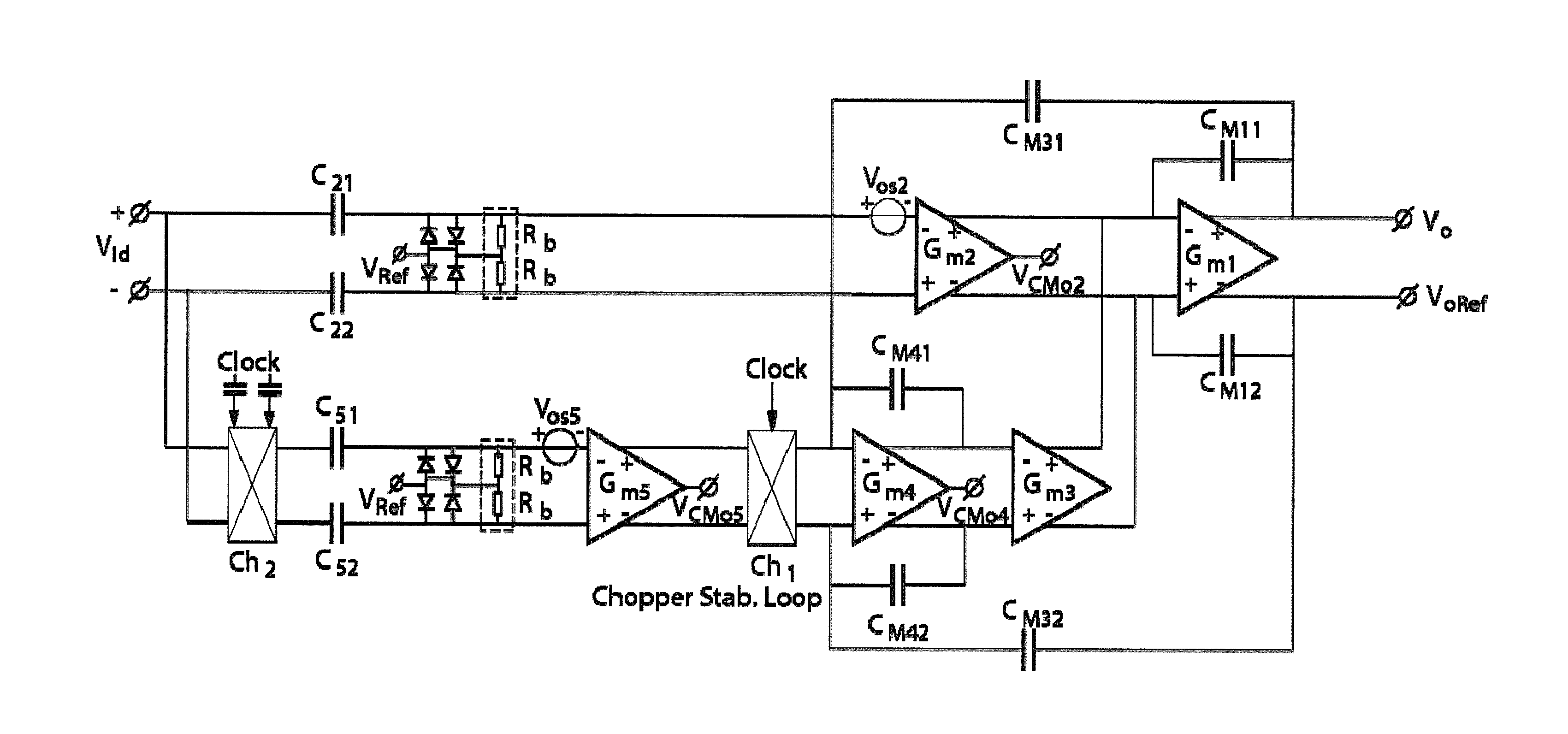
[0027]The present innovation allows measuring signals in Wide Band applications, meaning approaching the chopper frequency or beyond the chopper frequency without a slow-settling or non-settling chopper ripple response.

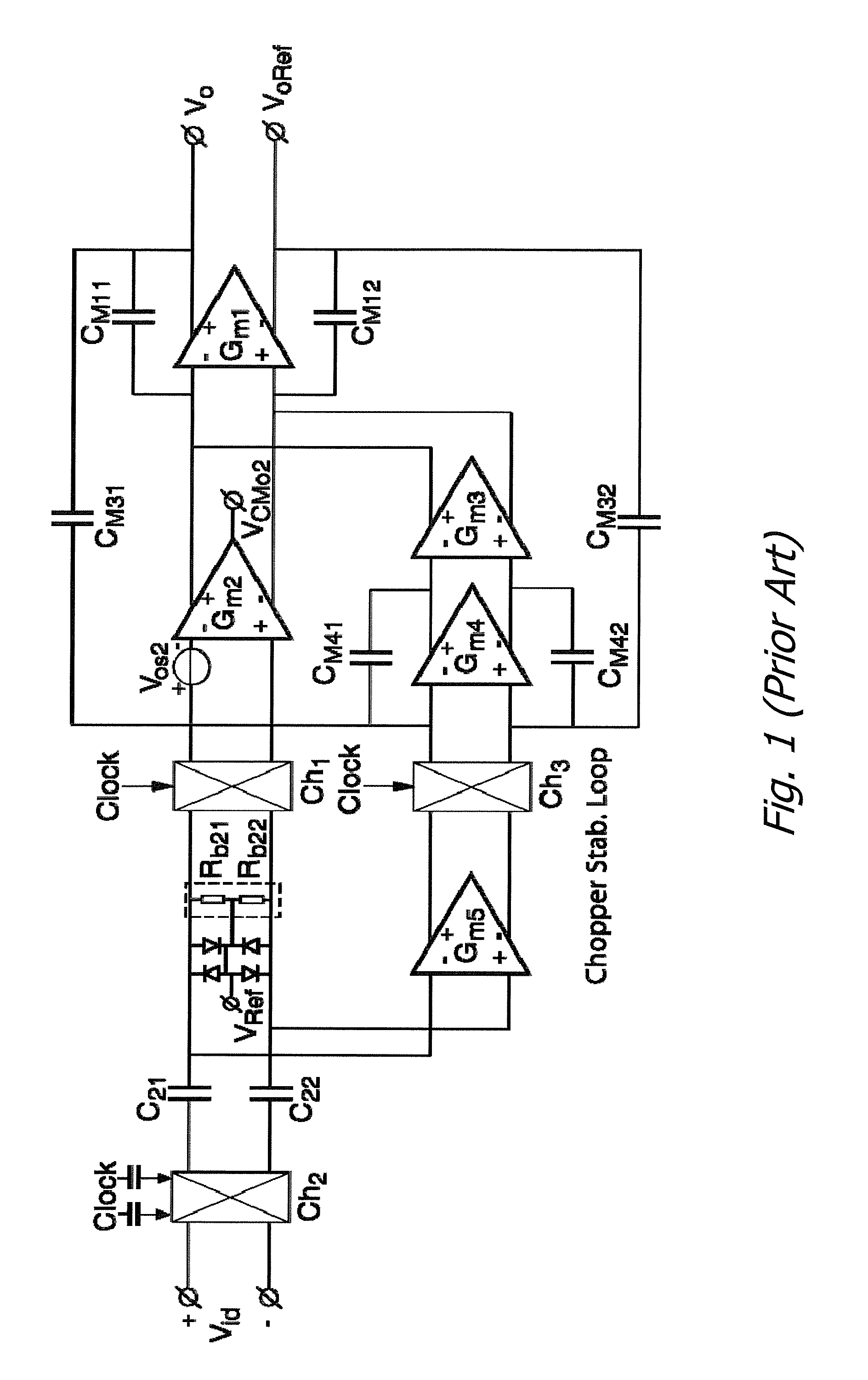
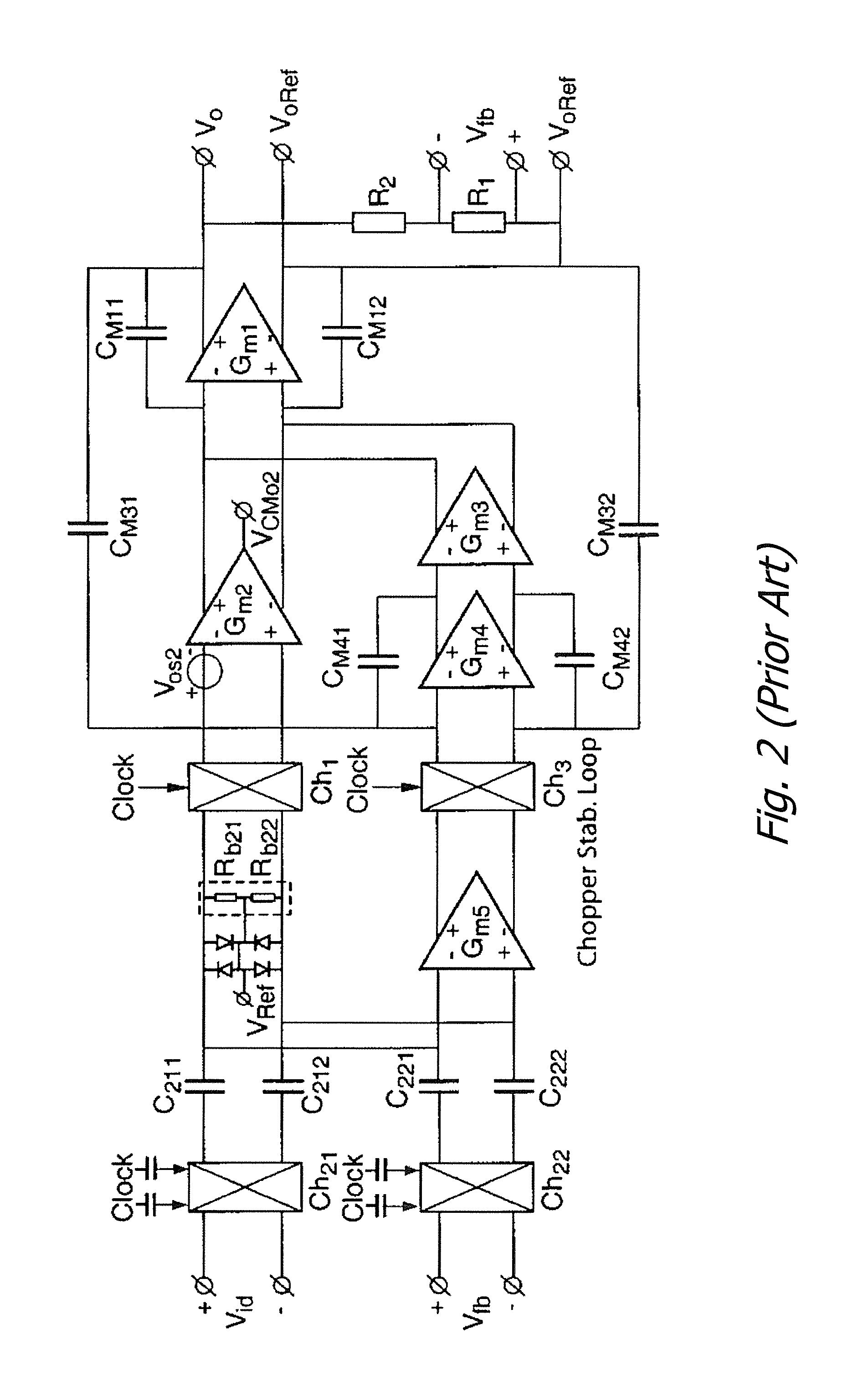
[0028]For a design of fast-settling capacitive-coupled amplifiers, reference is made to the chopper-stabilized amplifiers of Chapter 10.7 of “Operational Amplifiers, Theory and Design, Second Edition” (Johan Huijsing, 2011), such as the amplifier of FIG. 6, and to the chopper-stabilized chopper amplifiers of Chapter 10.8, such as in FIG. 7. These amplifiers have a straight frequency characteristic at the chopping frequency and basically no slow settling chopper ripple for a step function, meaning that their bandwidth is useful at much higher frequencies than the chopping frequency.

[0029]From the chopper-stabilized amplifier of FIG. 6, the two-path capacitive-coupled amplifier of FIG. 8 is derived. It has a high frequency path through Gm2 that includes the chopper freq...


PUM


Abstract

Fast-settling capacitive-coupled amplifiers are disclosed. The amplifiers use two Capacitive Coupled paths embedded in a Multipath Hybrid Nested Miller Compensation topology. One path is a direct high frequency path and the other path is a slower stabilization path. This combination results in a flat frequency response to and through the chopper frequency, and a fast settling response. Various exemplary embodiments are disclosed, including operational amplifier and instrumentation amplifier configurations.

Description

BACKGROUND OF THE INVENTION[0001]1. Field of the Invention[0002]The present invention relates to the field of fast settling amplifiers.[0003]2. Prior Art[0004]In current-sense applications for power management of cell phones, laptops, or electric cars, a small differential-mode (DM) voltage (in the order of mVolts) has to be measured across a current-sense resistor, in the presence of a large common-mode (CM) voltage on the sense resistor on the order of Volts or tens of Volts higher than the amplifier supply voltage. Instrumentation amplifiers (IAs) are frequently used for sensor interfacing. To solve the DM voltage measurement while the CM voltage is beyond the supply-rail, often a part of the input circuitry such as a resistor bridge or a voltage-to-current converter is allowed to draw its CM supply current from the sense resistor. This input CM supply current often has an undesired influence on the system to be measured. Therefore, IAs with capacitive-coupled input choppers have...

Claims


Application Information

Patent Timeline
IPC IPC(8): H03F1/56H03F3/45
CPCH03F3/45071H03F1/56H03F1/14H03F3/387H03F3/45475H03F2200/135H03F2200/459H03F2203/45458
Inventor HUIJSING, JOHAN HENDRIKFAN, QINWENMAKINWA, KOFI AFOLABI ANTHONYFU, DAIHONGWU, JUNZHOU, LIXIA
Owner MAXIM INTEGRATED PROD INC
Why Eureka
Try Eureka