Spark-ignition engine

a technology of spark ignition and spark plug, which is applied in the direction of combustion engines, internal combustion piston engines, machines/engines, etc., can solve the problems of increasing and achieve the effect of reducing the content of hydrocarbon in exhaust gas

Active Publication Date: 2014-08-28
KUBOTA LTD
View PDF7 Cites 10 Cited by
  • Summary
  • Abstract
  • Description
  • Claims
  • Application Information

AI Technical Summary

Benefits of technology

[0008]An object of the present invention is to provide a spark-ignition engine capable of reducing the content of hydrocarbon in exhaust gas.

Problems solved by technology

However, according to the conventional art, a spark discharge section at a tip of the spark plug is disposed at a position in the vicinity of a compression top dead center directly hit by a largest squish flow ejected from a squish area maximum-width section, which is disadvantageous.
Problem: The content of hydrocarbon in exhaust gas increases.

Method used


Image

  • Spark-ignition engine
  • Spark-ignition engine
  • Spark-ignition engine

Examples


first embodiment

[0065]The First embodiment will be described below. A summary of the engine is as follows.

[0066]As shown in FIG. 9, a cylinder head (1) is assembled to the upper part of a cylinder block (42), a cylinder head cover (43) is assembled to the upper part of the cylinder head (1), an engine cooling fan (44) is disposed in front of the cylinder block (42), and a flywheel (45) is disposed in the rear of the cylinder block (42).

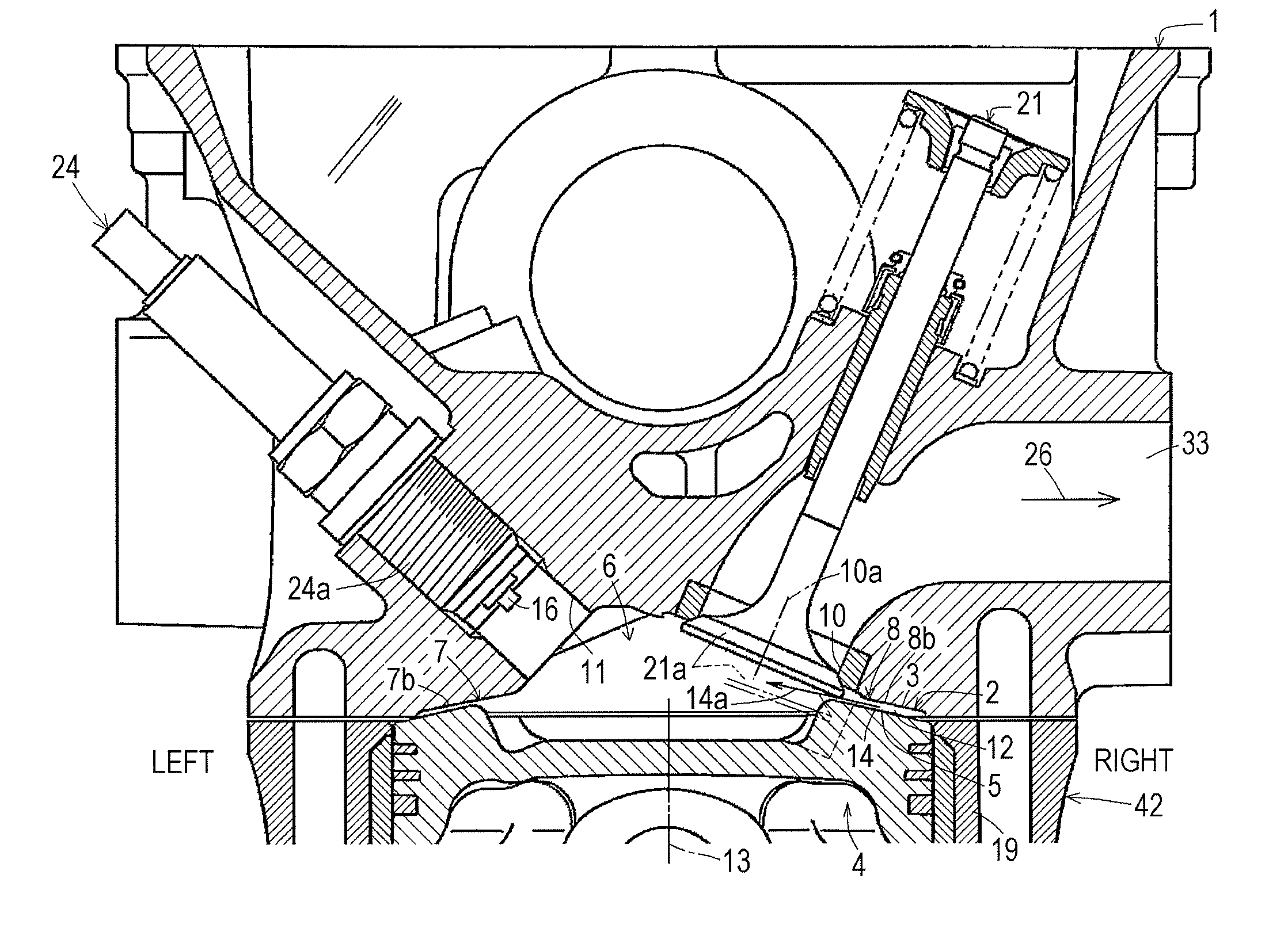
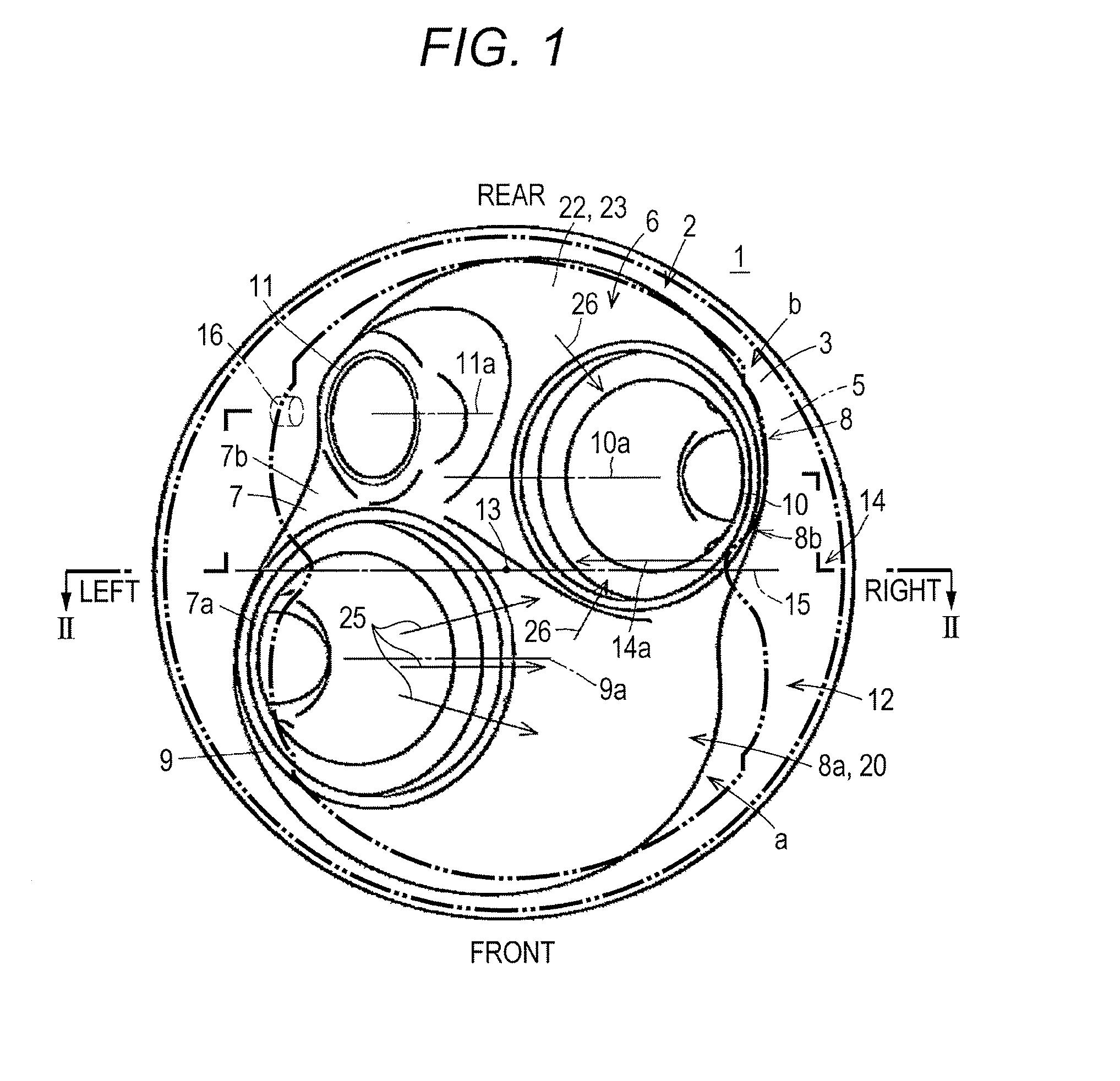
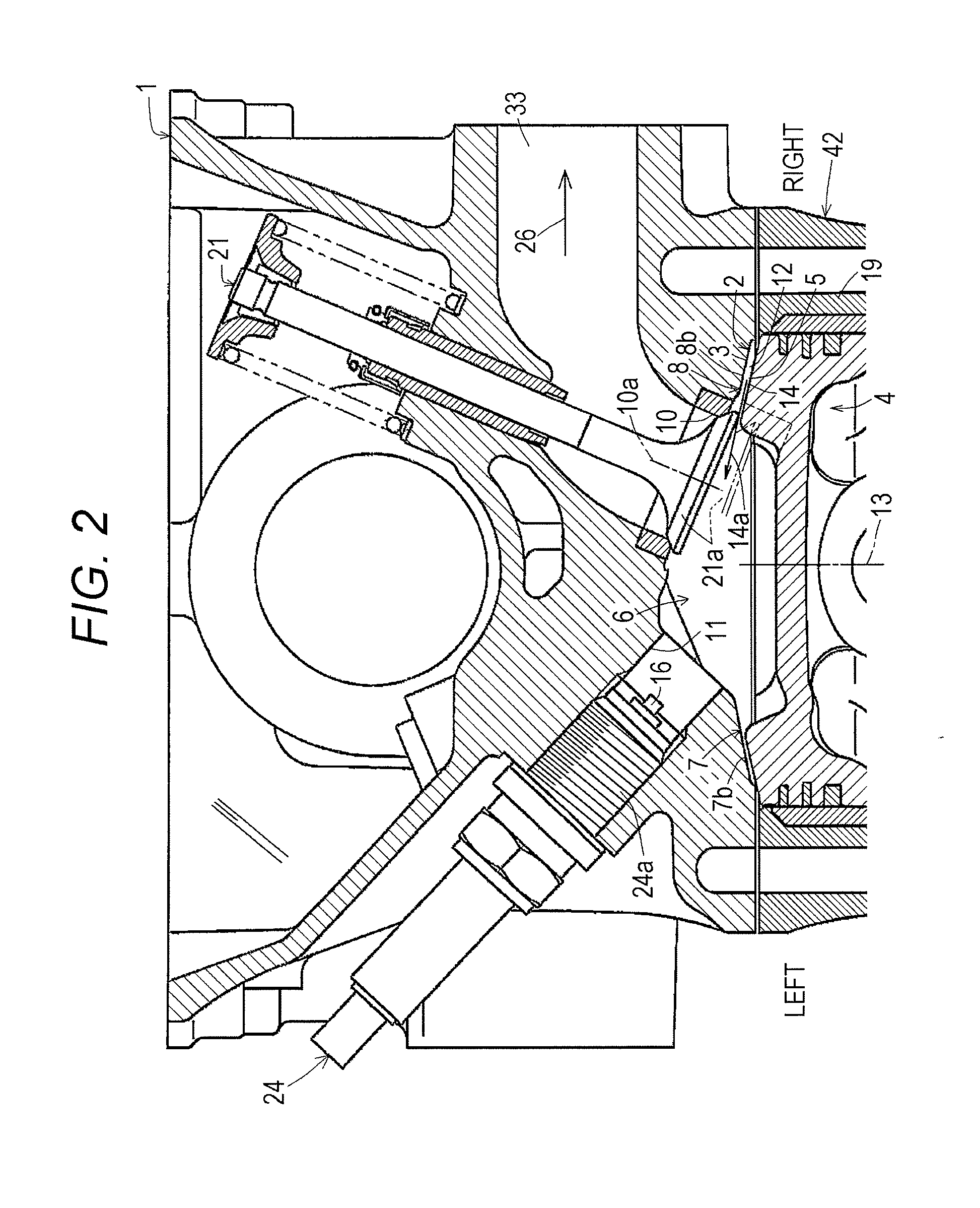
[0067]A throttle body (29) is assembled to the left side surface of the cylinder head (1), a fuel injector (30) is assembled to the throttle body (29), and a mechanical governor 46 is disposed on the left side of the cylinder block (42). As shown in FIG. 8, the cylinder block (42) is provided with a pair of front and rear cylinders (19)(19), and a piston head (4) is fitted into each cylinder (19). A crank shaft 48 is mounted in a crank case 47 of the cylinder block (42), and the crank pin angle of a pair of front and rear crank pins (49)(49) of the crank shaft 48 is ...

second embodiment

[0117]Next, Second embodiment will be described.

[0118]Second embodiment is different from First embodiment only in following points.

[0119]As shown in FIGS. 10(A) and 10(B), a pair of right and left squish area maximum-width sections (14) are provided.

[0120]As shown in FIGS. 10(A) and 10(B), a spark-plug recessed section (18) is formed in the opposed section (7) having the spark-plug attachment hole (11), out of the opposed sections (7)(8) of the combustion chamber recessed section (6).

[0121]The spark-plug attachment hole (11) is opened at the bottom end of the spark-plug recessed section (18).

[0122]As shown in FIG. 10(A), when viewed from the direction parallel to the cylinder center axis (13), the spark-plug recessed section (18) is provided in a position not to overlap the central virtual line (15).

[0123]As shown in FIG. 10(B), an inner circumferential surface (18a) of the spark-plug recessed section (18) has a central axis (11a) in common with the spark-plug attachment hole (11),...

third embodiment

[0126]Next, Third embodiment will be described.

[0127]As shown in FIG. 12, Third embodiment is different from First embodiment in that the exhaust treatment member (35) is disposed in the exhaust inlet (34d) of the exhaust muffler body (34c), and a circumferential wall (34e) of the exhaust inlet (34d) of the exhaust muffler body (34c) into which the exhaust treatment member (35) is incorporated is disposed along the circumferential wall (36c) of the branch section (36b) of the exhaust manifold (36).

[0128]The other configuration of this embodiment is the same as that of First embodiment, and the same constituents in FIG. 12 as those in First embodiment are given the same reference numerals as in FIG. 7.

[0129]The configuration of the exhaust treatment member (35) in Third embodiment may be applied to Second embodiment.

[0130]Examples of stainless steel that can be preferably used for the exhaust treatment member (35) in each of the embodiments include SUS316 defined in JIS (Japanese Ind...


PUM


Abstract

A spark-ignition engine capable of reducing the content of hydrocarbon in exhaust gas is provided. When viewed from a direction parallel to a cylinder center axis, given a central virtual line passing a squish area maximum-width section and the center of a combustion chamber recessed section, and one area a and the other area b divided by the central virtual line, an intake valve port or an exhaust valve port is opened in one area of any opposed section of opposed sections of the combustion chamber recessed section. A spark-plug attachment hole is formed in the other area of the opposed section, such that, when viewed from the direction parallel to the cylinder center axis, a spark discharge section at a tip of a spark plug does not overlap the central virtual line.

Description

BACKGROUND OF THE INVENTION[0001]1. Field of the Invention[0002]The present invention relates to a spark-ignition engine, and in particular, to a spark-ignition engine capable of reducing the content of hydrocarbon in exhaust gas.[0003]2. Description of Related Art[0004]A conventional spark-ignition engine includes a cylinder head-side squish surface provided on the outer periphery of a combustion chamber roof of a cylinder head, a piston head-side squish surface provided on the outer periphery of a piston head as opposed to the cylinder head-side squish surface, a combustion chamber recessed section recessed at the center of the combustion chamber roof of the cylinder head, an intake valve port provided on one opposed section of opposed sections of the combustion chamber recessed sections, an exhaust valve port provided on the other opposed section, and a spark-plug attachment hole facing the combustion chamber recessed section, in which the cylinder head-side squish surface and th...

Claims


Application Information

Patent Timeline
Patent Type & Authority Applications(United States)
IPC IPC(8): F02B75/12
CPCF02B75/12F02B23/08Y02T10/12
Inventor NAKASHIMA, EISHINOKANO, SHUNJIKAWASOE, HIROYUKIOHASHI, TAMOTSUINOUE, NAOKIOZAKI, YUKI
Owner KUBOTA LTD
Why Eureka
Try Eureka