
Wheel loader

a technology of loader and loader body, which is applied in the direction of machines/engines, mechanical equipment, transportation and packaging, etc., can solve the problems of deterioration of reducing agents, so as to suppress excessive rise in temperature inside the engine room and achieve the effect of reducing the effect of temperature ris

Inactive Publication Date: 2014-08-28
KOMATSU LTD
View PDF82 Cites 25 Cited by
  • Summary
  • Abstract
  • Description
  • Claims
  • Application Information

AI Technical Summary

Benefits of technology

The patent aims to prevent the engine room from overheating. The technical effect of this invention is to suppress the temperature inside the engine room from rising too much.

Problems solved by technology

However, there is a problem in that the temperature inside the engine room rises excessively since these devices generate heat while operating.
Problems such as the deterioration of a reducing agent such as urea water used in the selective catalyst reduction device occur when the temperature inside the engine room rises excessively.
The visibility to the rear is undesirably reduced when the top plate of the engine room is high.
Specifically, the temperature rises excessively inside the engine room that accommodates the diesel particulate filtering device and the selective catalyst reduction device since these devices generate heat while operating thus producing hot air.
There is a risk that rain could enter the engine room through the first ventilation part since the first ventilation part is formed in the top plate.
The cooling room generally does not accommodate any device that suffers from problems due to water intrusion.

Method used


Image

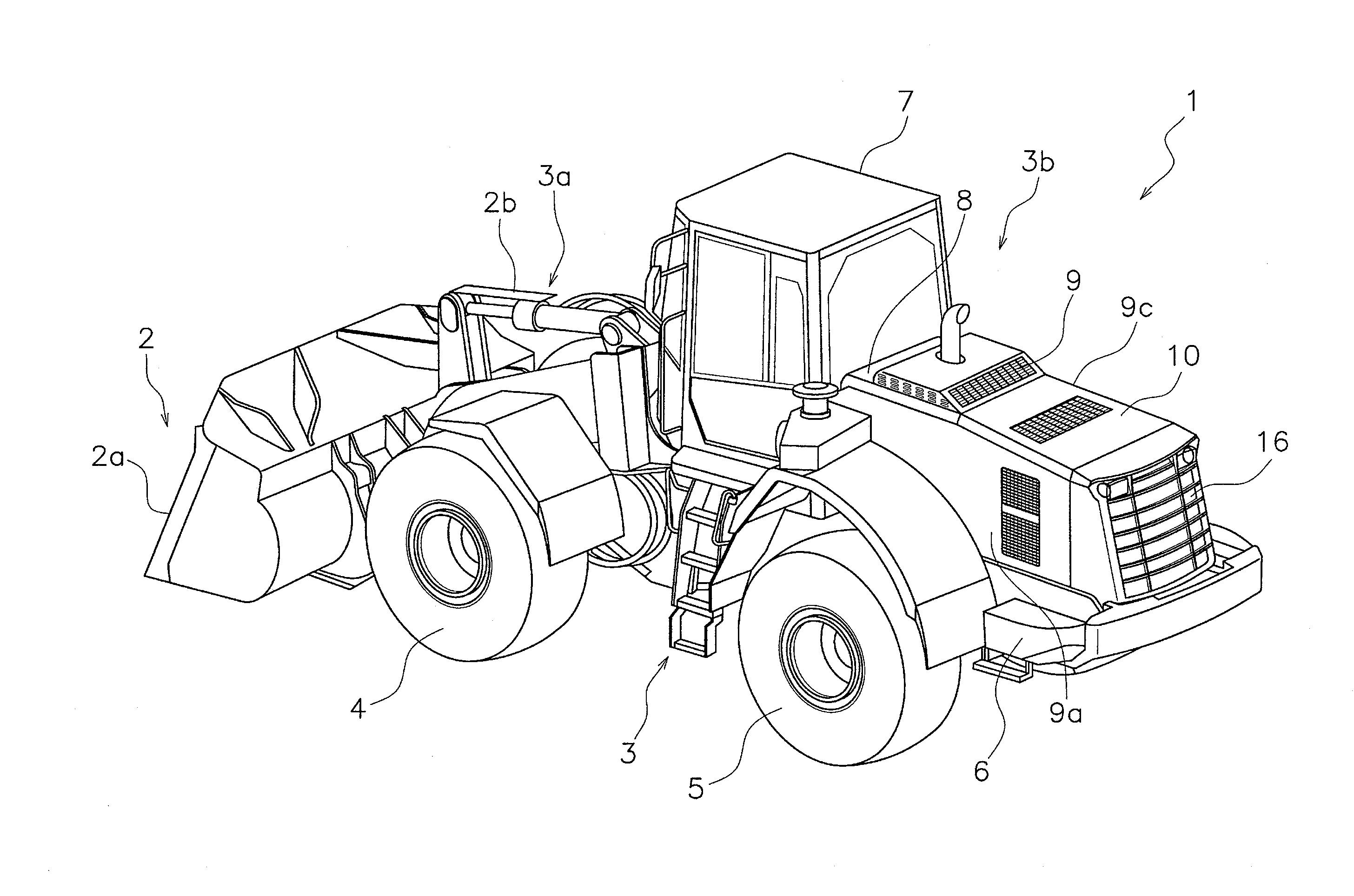
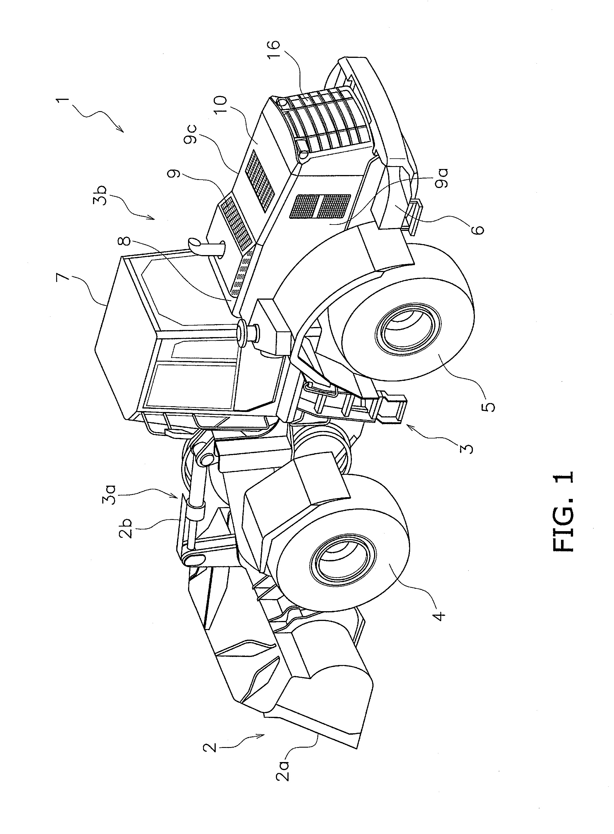
  • Wheel loader
  • Wheel loader
  • Wheel loader

Examples


modified examples

[0065]While an embodiment of the present invention has been described above, the present invention is not limited to the embodiment and the following modifications may be made within the scope of the present invention.

modified example 1

[0066]The number of water conveyance members 15b is not limited to two, and one or three or more may be provided. The receptacle member 15a has the same number of through-holes 15e as the number of water conveyance members 15b. If only one water conveyance member 15b is provided, then the receptacle member 15a has only one through-hole 15e and the water conveyance member 15b is provided under the through-hole 15e. The location of the through-hole 15e of the receptacle member 15a is preferably at the left rear edge part or the right rear edge part of the bottom plate 15c. This is because the rainwater collected on the receptacle member 15a gathers easily at the left rear edge part or the right rear edge part.

modified example 2

[0067]As illustrated in FIG. 9, the water conveyance member 15b may have a pipe-like member. A first edge part of the water conveyance member 15b is linked to the through-hole 15e of the receptacle member 15a, and a second edge part is linked to the water drainage outlet of the partition wall 9b. The water conveyance member 15b may pass through the water drainage outlet 9r of the partition wall 9b so that the second edge part is located in the cooling room 10.


PUM


Abstract

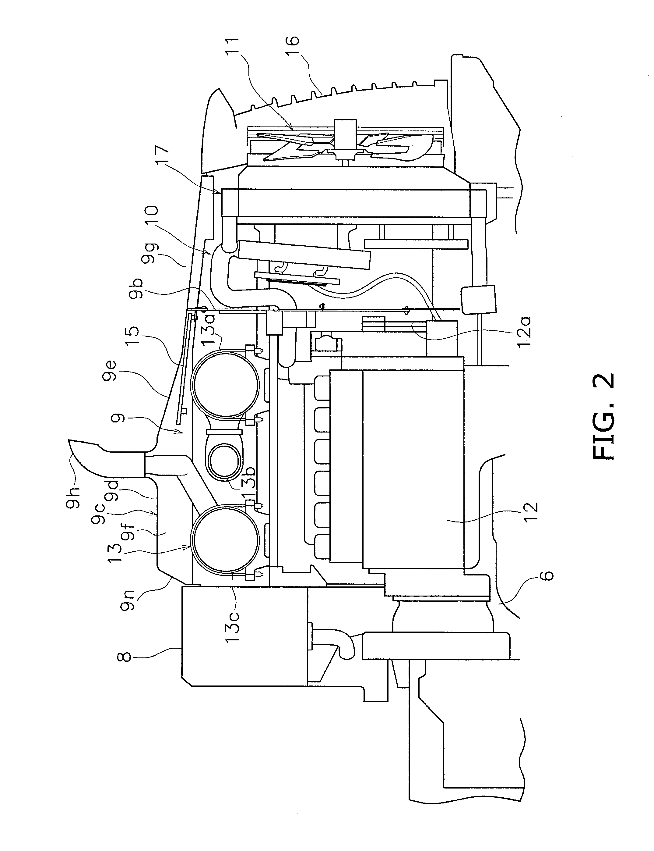
A wheel loader comprises an engine, an exhaust gas post-processing device, an engine room, a top plate, a cooling room, a partition wall, and a drainage mechanism. The exhaust gas post-processing device is disposed above the engine in the engine room and includes a diesel particulate filtering device and a selective catalyst reduction catalyst device. The top plate has a sloping part with a height that decreases toward the rear, and a first ventilation part that includes a plurality of through-holes formed in the sloping part. The top plate defines an upper plane of the engine room. The cooling room accommodates a cooling unit and is disposed to the rear of the engine room, separated by the partition wall. The drainage mechanism is disposed below the first ventilation part, and configured to drain water entering the engine room from the first ventilation part to the outside of the engine room.

Description

CROSS-REFERENCE TO RELATED APPLICATIONS[0001]This application is a U.S. National stage application of International Application No. PCT / JP2013 / 054464 filed on Feb. 22, 2013.FIELD OF THE INVENTION[0002]The present invention relates to a wheel loader and in particular to a wheel loader having an exhaust gas post-processing device above an engine.DESCRIPTION OF THE RELATED ART[0003]A wheel loader is equipped with an engine room accommodating an engine to the rear of a cab (Japanese Laid-Open Patent Publication No. H8-276755). Recently, exhaust gas post-processing devices have been mounted on wheel loaders for processing exhaust gas from the engine. The exhaust gas post-processing device includes mainly a diesel particulate filtering device, and is usually accommodated inside the engine room. A hydraulic excavator described in Japanese Laid-open Patent Publication No. 2011-140853 is provided with a nitrogen oxide purifying device as a selective catalyst reduction device as the exhaust g...

Claims


Application Information

Patent Timeline
Patent Type & Authority Applications(United States)
IPC IPC(8): B60K13/04B60K11/02
CPCB60K13/04B60K11/02E02F9/0866E02F9/0891E02F3/3411F01N3/2066F01N3/021F01N2340/04F01N2590/08B60K11/04B60Y2200/412Y02A50/20Y02T10/12
Inventor NUMA, YASUTAKA
Owner KOMATSU LTD
Learn More