Electronic part and electronic control unit

a technology of electronic control unit and electronic part, which is applied in the direction of printed circuit aspects, high current circuit adaptation, printed circuit non-printed electric components association, etc., can solve the problems of difficult to make a size of printed board and electronic control unit correspondingly reduced, and the size of printed board can be reduced. , the effect of reducing the manufacturing cos

Active Publication Date: 2014-08-28
DENSO CORP +1
View PDF2 Cites 9 Cited by
  • Summary
  • Abstract
  • Description
  • Claims
  • Application Information

AI Technical Summary

Benefits of technology

[0008]The present disclosure is made in view of the above problems. It is an object of the present disclosure to provide an electronic part and an electronic control unit having the electronic part, according to which it is possible to commonalize and / or standardize a printed board, to which the electronic parts are mounted, and to make a size of the printed board smaller. In addition, it is another object of the present disclosure to improve response of cutting-off performance between short-circuit of the electronic part and cut-off of excess current.

Problems solved by technology

As a result, it is difficult to commonalize or standardize the printed boards for different types of electronic control units.
In other words, it is difficult to commonalize the printed boards and to simply change the electronic parts to be mounted to the printed board in order to use the same type of the printed board for the different types of the electronic control units (variation products).
In addition, it is difficult to make a size of the printed board as well as the electronic control unit smaller, because the pattern fuse (or pattern fuses) is provided on the printed board as a part of the wiring patterns.
Since the heat of the pattern fuse goes away to the insulating board as above, it is a problem that it may take a longer time from short-circuit in the electronic part to melt-down of the pattern fuse.
In other words, it is not possible to quickly cut off the pattern fuse with high response.
In addition, since response characteristics vary, it is not possible to assure accuracy of performance for cutting off the pattern fuse.

Method used


Image

  • Electronic part and electronic control unit
  • Electronic part and electronic control unit
  • Electronic part and electronic control unit

Examples


first embodiment

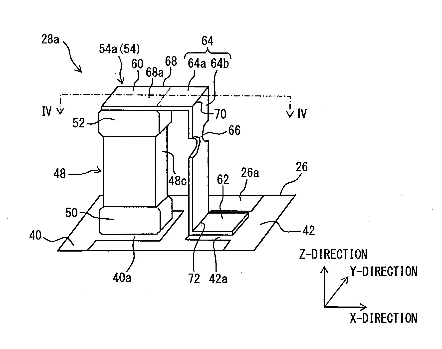
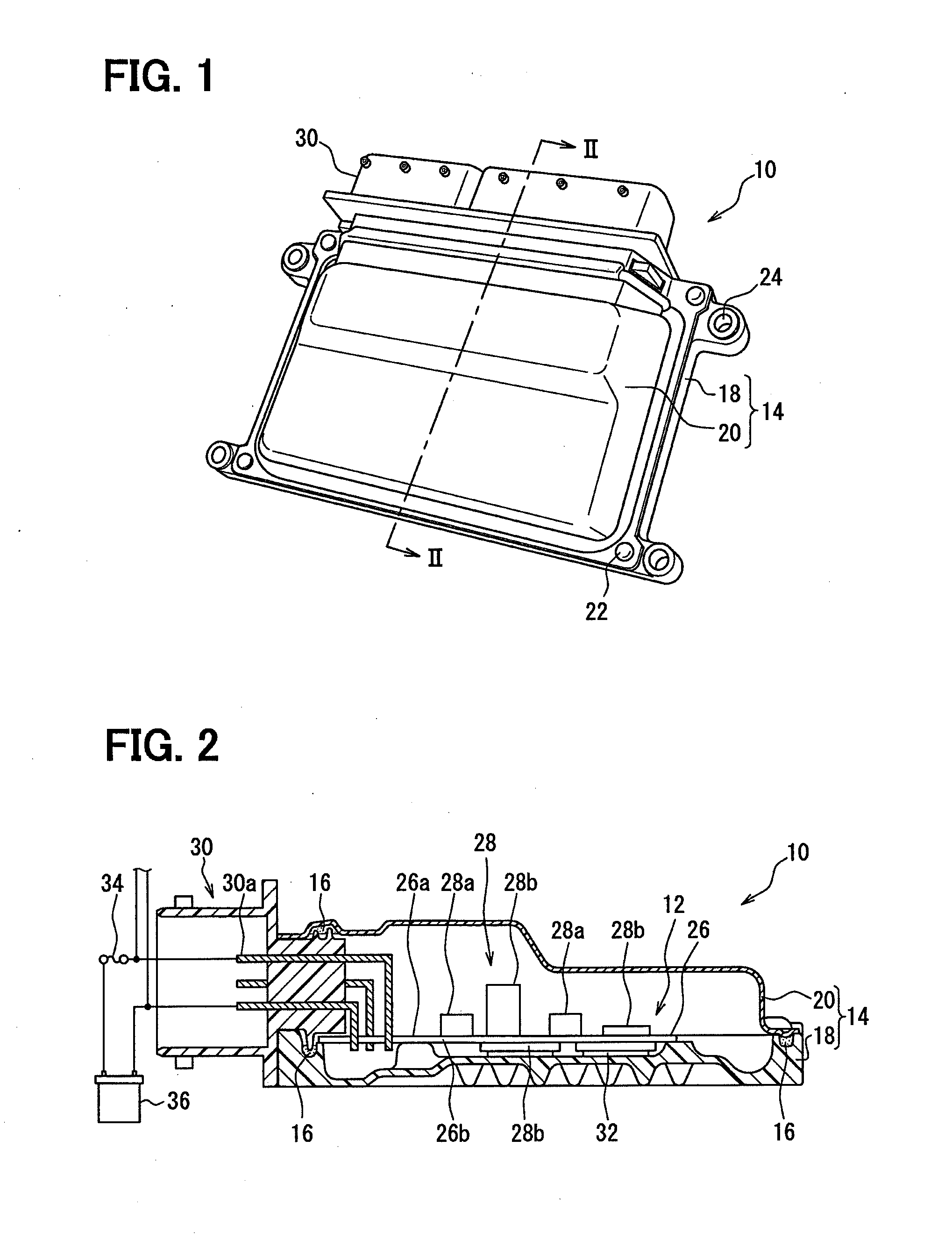
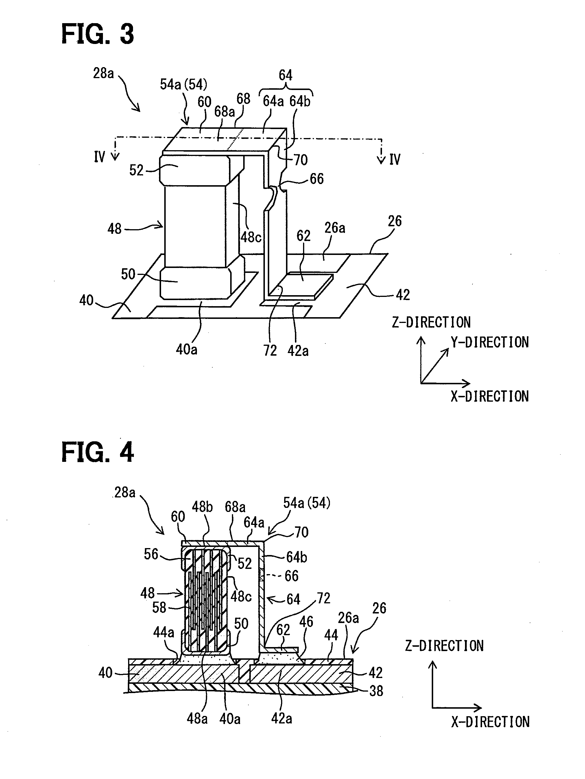
[0045]An electronic control unit 10 shown in FIGS. 1 and 2 has a circuit board 12 as a main part thereof. The electronic control unit 10 further has a housing 14 for accommodating the circuit board 12 and a seal element 16. In the present embodiment, the electronic control unit 10 is formed as an electronic control unit (ECU) of a water-proof type for controlling an operation of an engine for a vehicle.

[0046]An outline structure for the electronic control unit 10 will be hereinafter explained.

[0047]The housing 14 is made of metal, such as, aluminum, iron or the like, or resin material, for accommodating therein the circuit board 12 so as to protect the same from water, dust and so on. A number of parts for forming the housing 14 is not limited to a specific number, so that the housing 14 may be composed of one or multiple members.

[0048]As shown in FIG. 2, according to the present embodiment, the housing 14 is composed of two parts, that is, a lower casing 18 of a shallow-box shape h...

second embodiment

[0097]A second embodiment of the present disclosure will be explained with reference to FIG. 10. Explanation for those portions, which are similar to or the same to those of the first embodiment (including the electronic part 28a, the electronic control unit 10 and so on), will be omitted.

[0098]As shown in FIG. 10, the second embodiment has a first technical feature different from the first embodiment, according to which an arm portion 78 is provided in the fuse terminal 54a. In addition, the second embodiment has a second technical feature different from the first embodiment, according to which the cut-off portion 66 is formed in the connecting portion 64 between the first connecting part 64a and the arm portion 78, that is, at a position closer to the electrode-connected portion 60.

[0099]The arm portion 78 extends from the second connecting part 64b of the connecting portion 64 in the X-direction, that is, a direction perpendicular to the second connecting part 64b of the connecti...

third embodiment

[0105]A third embodiment will be explained with reference to FIG. 12. Explanation for those portions, which are similar to or the same to those of the first and / or second embodiments (including the electronic part 28a, the electronic control unit 10 and so on), will be omitted.

[0106]As shown in FIG. 12, a wiring member 80 is provided in a place of the second wiring pattern 42 of the second embodiment, wherein the wiring member 80 is made as an independent part from the printed board 26. The other portions and structure of the third embodiment are the same to those of the second embodiment (the fourth modification shown in FIG. 11).

[0107]The wiring member 80 is, for example, a bus bar made of metal through which large current flows. The land-connected portion 62 of the fuse terminal 54a is connected (soldered) to the wiring member 80. The wiring member 80 (FIG. 12) and the second wiring pattern 42 (for example, FIG. 11) are collectively referred to as a second wiring portion. In FIG....


PUM


Abstract

A main body of an electronic part is formed in a rectangular pillared shape having a first and a second axial end surface. A first electrode is formed on the first axial end surface electrically and mechanically connected to a first wiring pattern formed on a board surface of a printed board. A second electrode is formed on the second axial end surface, to which one end of a fuse terminal is electrically connected. The other end of the fuse terminal is connected to a second wiring pattern of the printed board or a wiring member which is formed as an independent member from the printed board. A cut-off portion is formed in a connecting portion of the fuse terminal.

Description

CROSS REFERENCE TO RELATED APPLICATION[0001]This application is based on Japanese Patent Application No. 2013-038363 filed on Feb. 28, 2013, the disclosure of which is incorporated herein by reference.FIELD OF TECHNOLOGY[0002]The present disclosure relates to an electronic part mounted to a printed board and an electronic control unit having the electronic part.BACKGROUND[0003]A printed board having a pattern fuse, which is a part of wiring patterns formed in the printed board, is known in the art, for example, as disclosed in Japanese Patent Publication No. 2007-311467.[0004]The pattern fuse is generally so formed as to be narrower than a remaining part of the wiring patterns. Therefore, for example, when a short-circuit occurs in an inside of an electronic device or an electronic part and thereby excess current flows, the pattern fuse is melted down due to heat generation in order that an electric pathway is cut off.[0005]In a case of the pattern fuse, it is necessary to individua...

Claims


Application Information

Patent Timeline
Patent Type & Authority Applications(United States)
IPC IPC(8): H01H85/02H05K1/18
CPCH01H85/0241H05K1/18H01H85/10H01H2085/0275H05K1/0263H05K1/181H05K3/3426H05K2201/10181H05K2201/10454H05K2201/10946H01G2/16H01G2/18H01H69/022H01H85/463H01H85/48H01H85/50
Inventor ITABASHI, TORUMIKAMI, YUKISHIRAISHI, RYOICHIYANAGISAWA, AKIHIRONISHIYAMA, SHIGEKI
Owner DENSO CORP
Why Eureka
Try Eureka