Feed forward parameter values for use in theoretically generating spectra

a parameter value and theoretical spectra technology, applied in the field of optical monitoring, can solve the problems of low reliability or requiring other techniques, complex optical models with a large number of variable input parameters can suffer similar problems of computational load, and possible false fitting of optical parameters, so as to reduce the size of the library, reduce the processing load for calculation of the layer stack, and improve the reliability of the endpoint system to detect a desired polishing endpoint

Inactive Publication Date: 2014-08-28
APPLIED MATERIALS INC
View PDF24 Cites 13 Cited by
  • Summary
  • Abstract
  • Description
  • Claims
  • Application Information

AI Technical Summary

Benefits of technology

[0012]Certain implementations can include one or more of the following advantages. A library of reference spectra that spans the likely range of variations of incoming substrates can be calculated from an optical model. The size of the library may be reduced if a variable parameter is replaced by a known value. The variable can be determined from an upstream measurement before polishing or measurement at an in-line monitoring station. Thus, reliability of the endpoint system to detect a desired polishing endpoint may be improved, and within-wafer and wafer-to-wafer thickness non-uniformity (WIWNU and WTWNU) may be reduced. Additionally, the information can be used for in-sequence monitoring to determine the polish time / pressures for the next platen or for a rework. In addition, processing load for calculation of the layer stacks can be reduced. Additionally, prediction accuracy can increase as a set of parameters are predetermined which reduces the chance of incorrect fits or correlations.

Problems solved by technology

The larger library may also produce multiple possible matches, causing lower reliability or requiring other techniques to sift the possible matches and select an acceptable match.
However, a complex optical model with a large the number of variable input parameters can suffer similar problems of computational load and possible false fitting of the optical parameters.

Method used


Image

  • Feed forward parameter values for use in theoretically generating spectra
  • Feed forward parameter values for use in theoretically generating spectra
  • Feed forward parameter values for use in theoretically generating spectra

Examples


Embodiment Construction

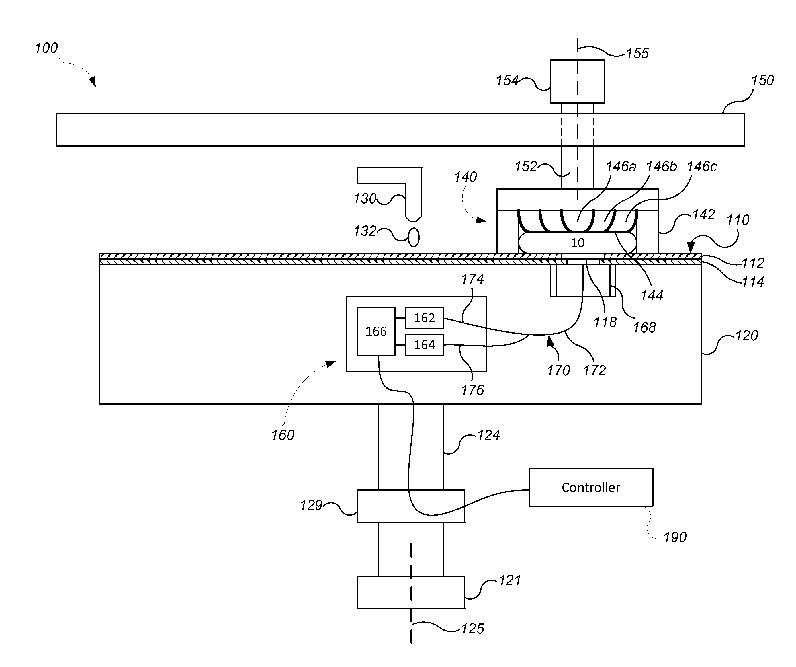
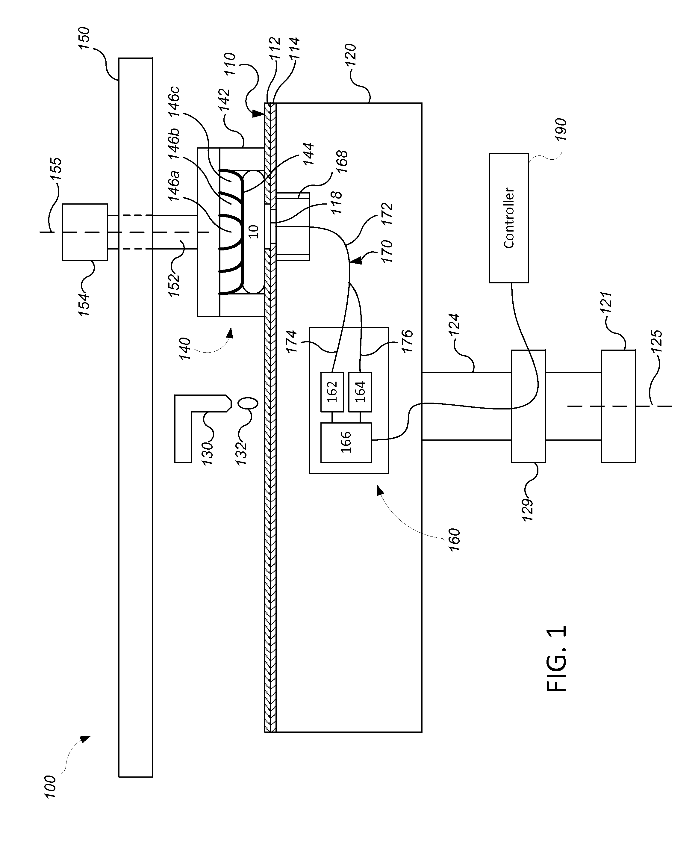
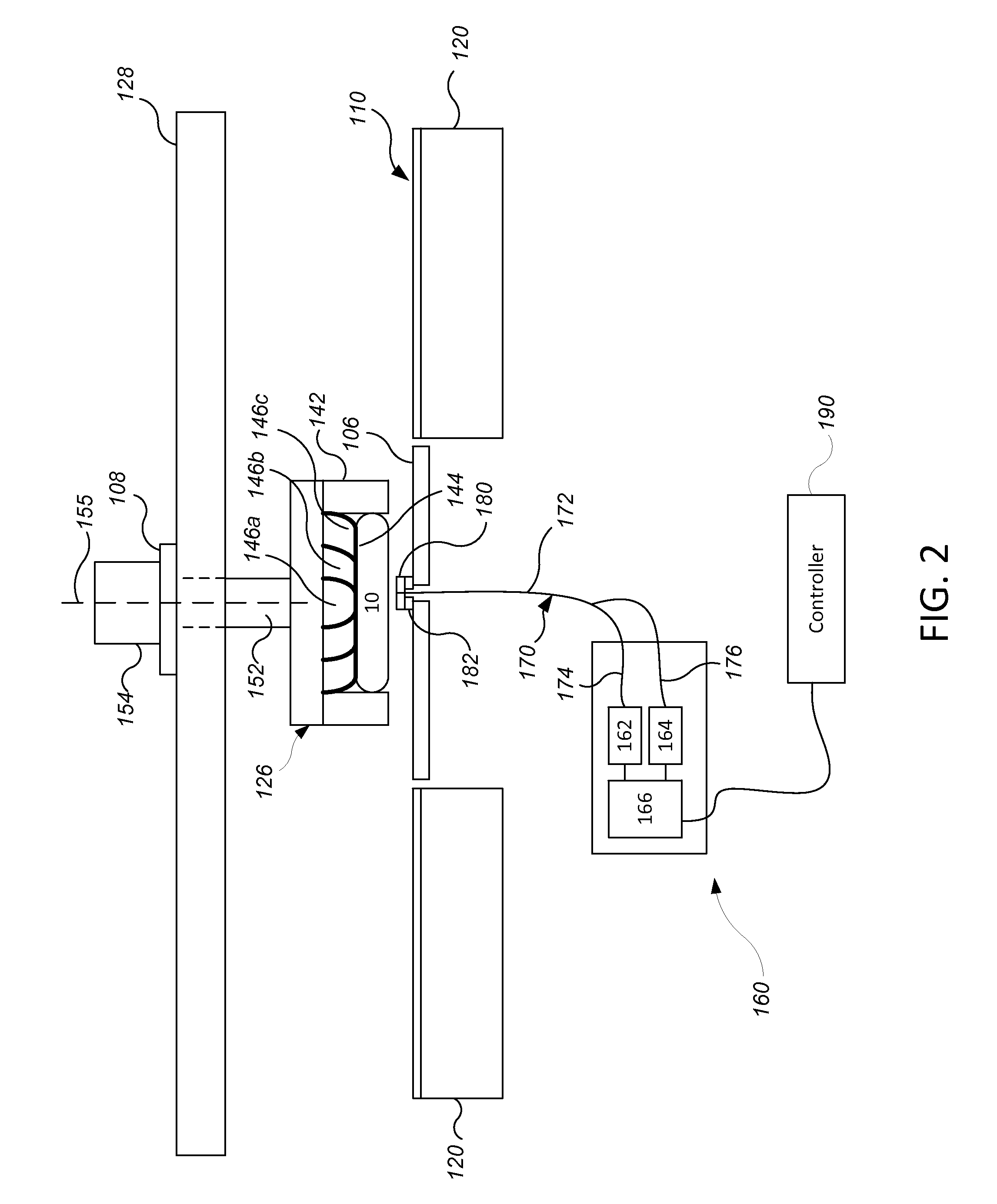
[0023]One optical monitoring technique for controlling a polishing operation is to measure a spectrum of light reflected from a substrate, either in-situ during polishing or at an in-line metrology station, and compare the measured spectrum to a plurality of reference spectra from a library, and identify a best-matching reference spectrum. The reference spectra can be calculated from an optical model by varying multiple input parameters. Ideally, the optical model has sufficient degrees of freedom to generate a library of reference spectra that spans the likely range of variation of incoming substrates.

[0024]One potential problem is the size of the library of reference spectra. For reliable polishing of some types of substrates, the library of reference spectra may have reference spectra that span the likely range of variations in thickness and / or other parameters of the underlying layers of incoming substrates, and consequently increasing the size of the library. In some examples, ...


PUM


Abstract

A method of controlling a polishing operation is described. A controller stores an optical model for a layer stack having a plurality of layers and a plurality of input parameters including a first parameter and a second parameter. The controller stores data defining a plurality of default values for the first parameter and measures an optical property of a substrate and generates a second value. Using the optical model and the second value and iterating over the first values, a number of reference spectra are calculated. A spectrum is measured and the measured spectrum is matched to the reference spectra and the best matched reference spectrum is determined. The first value of the best matched reference spectrum is determined and is used to adjust a polishing endpoint or a polishing parameter of a polishing apparatus.

Description

TECHNICAL FIELD[0001]The present disclosure relates to optical monitoring, e.g., for control of chemical mechanical polishing of substrates.BACKGROUND[0002]An integrated circuit is typically formed on a substrate by the sequential deposition of conductive, semiconductive, or insulative layers on a silicon wafer. One fabrication step involves depositing a filler layer over a non-planar surface and planarizing the filler layer. For certain applications, the filler layer is planarized until the top surface of a patterned layer is exposed. A conductive filler layer, for example, can be deposited on a patterned insulative layer to fill the trenches or holes in the insulative layer. After planarization, the portions of the conductive layer remaining between the raised pattern of the insulative layer form vias, plugs, and lines that provide conductive paths between thin film circuits on the substrate. For other applications, such as oxide polishing, the filler layer is planarized until a p...

Claims


Application Information

Patent Timeline
Patent Type & Authority Applications(United States)
IPC IPC(8): B24B37/013B24B49/12
CPCB24B49/12B24B37/013
Inventor DAVID, JEFFREY DRUEMENK, GREGORY E.BENNETT, DOYLE E.QIAN, JUNDHANDAPANI, SIVAKUMARCHERIAN, BENJAMINOSTERHELD, THOMAS H.SWEDEK, BOGUSLAW A.
Owner APPLIED MATERIALS INC
Why Eureka
Try Eureka