Heat exchanger

Inactive Publication Date: 2014-09-04
DENSO CORP
View PDF11 Cites 14 Cited by
  • Summary
  • Abstract
  • Description
  • Claims
  • Application Information

AI Technical Summary

Benefits of technology

[0044]According to this, all of the first fluid branched to the upstream heat exchange portion passes through the upstream heat exchange portion without further branching to the downstream heat exchange portion, and all of the first fluid branched to the downstream heat exchange portion passes through the downstream heat exchange portion without further branching to the upstream heat exchange portion. Hence, two flows of the first fluid, which are branched to the upstream heat exchange portion and the downstream heat exchange portion at a most upstream portion in a refrigerant flow direction, can be prevented from gathering together in the heat exchange portions. Therefore, decrease of a performance of the heat excha

Problems solved by technology

Although heat of the coolant flowing through the coolant passage can be transferred to the refrigerant passage adjacent to the coolant passage, the heat of the coolant cannot be transferred to whole area of refrigerant passages.
Such insufficient heat transfer

Method used


Image

  • Heat exchanger
  • Heat exchanger
  • Heat exchanger

Examples


first embodiment

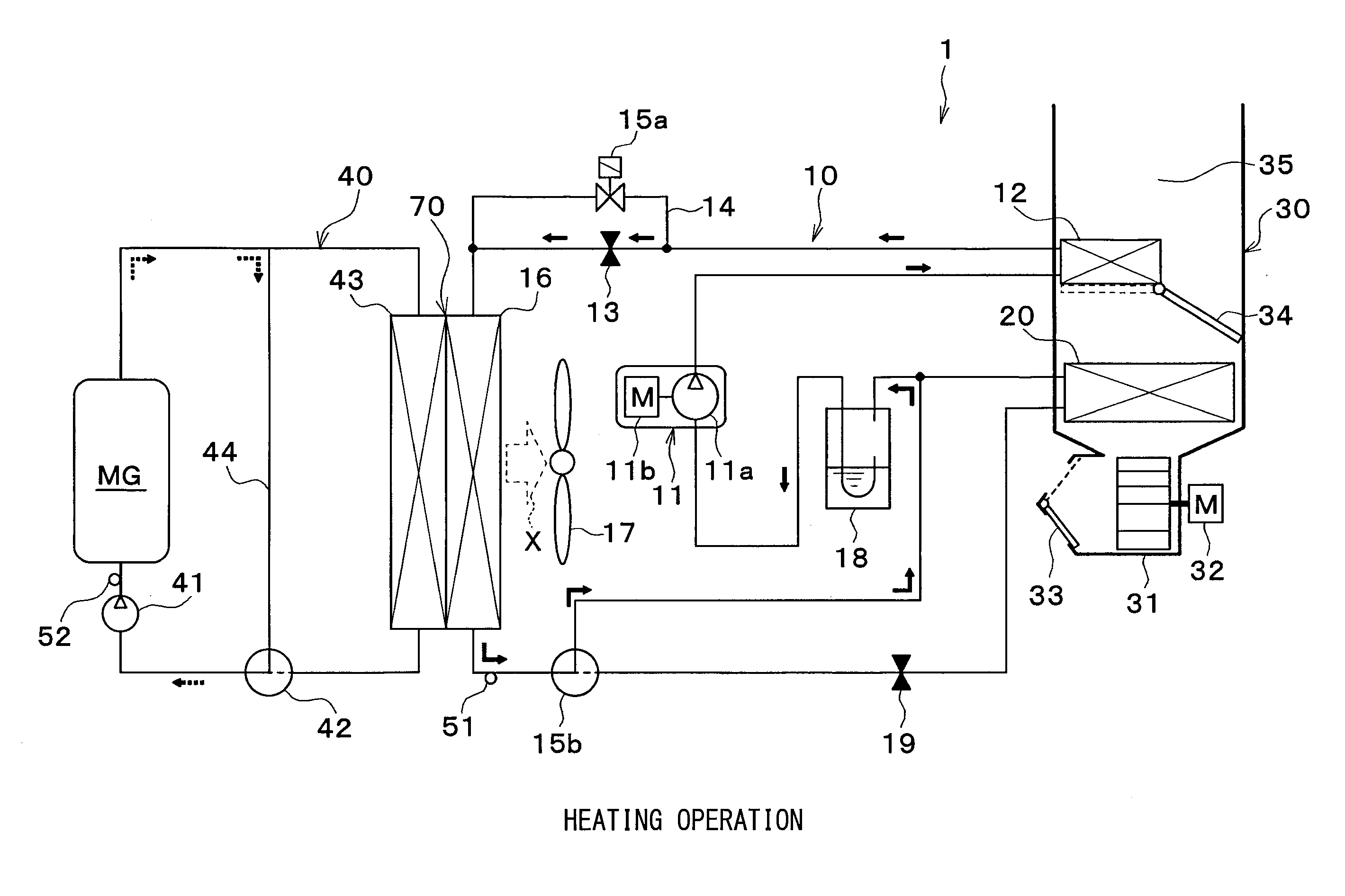
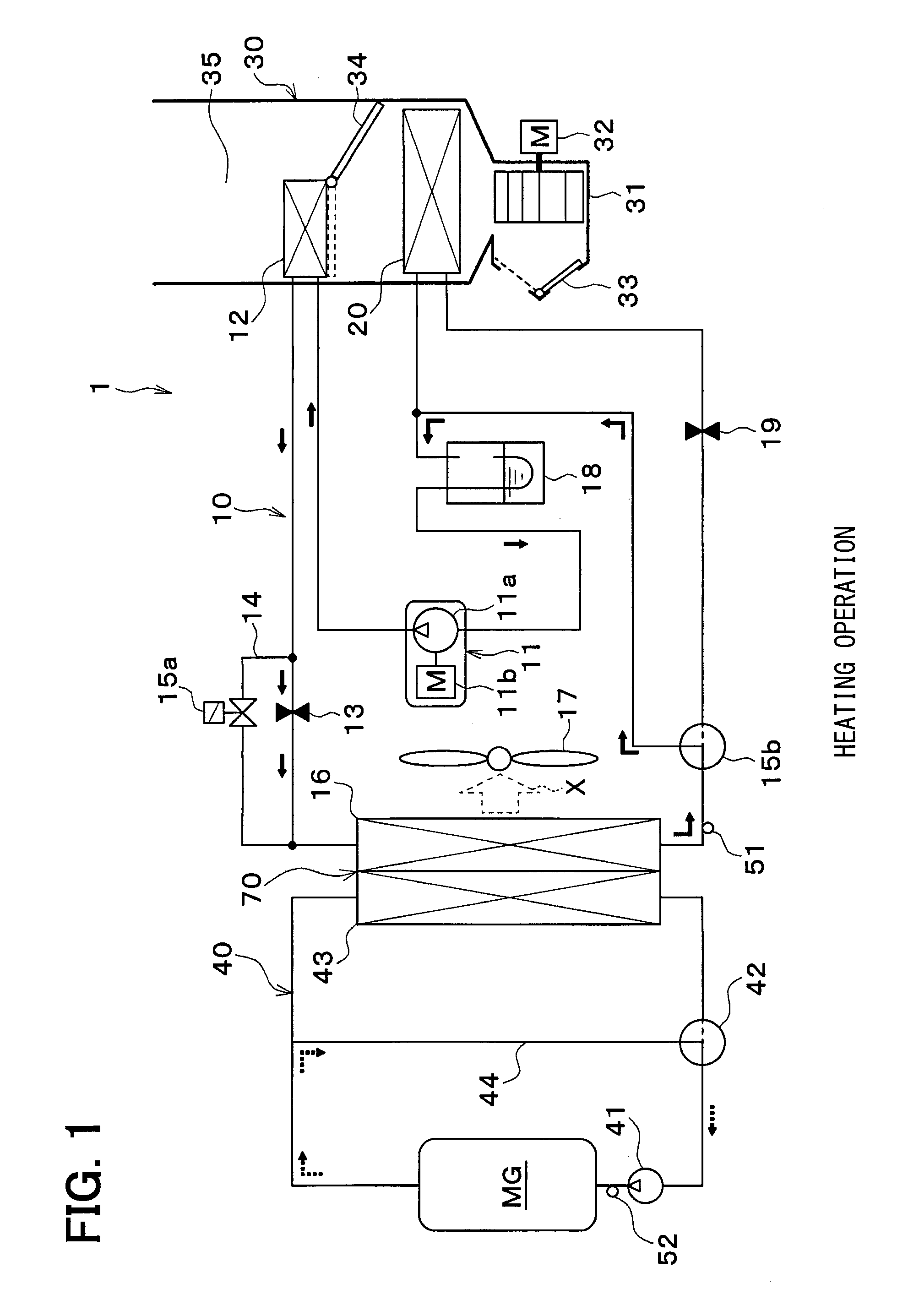
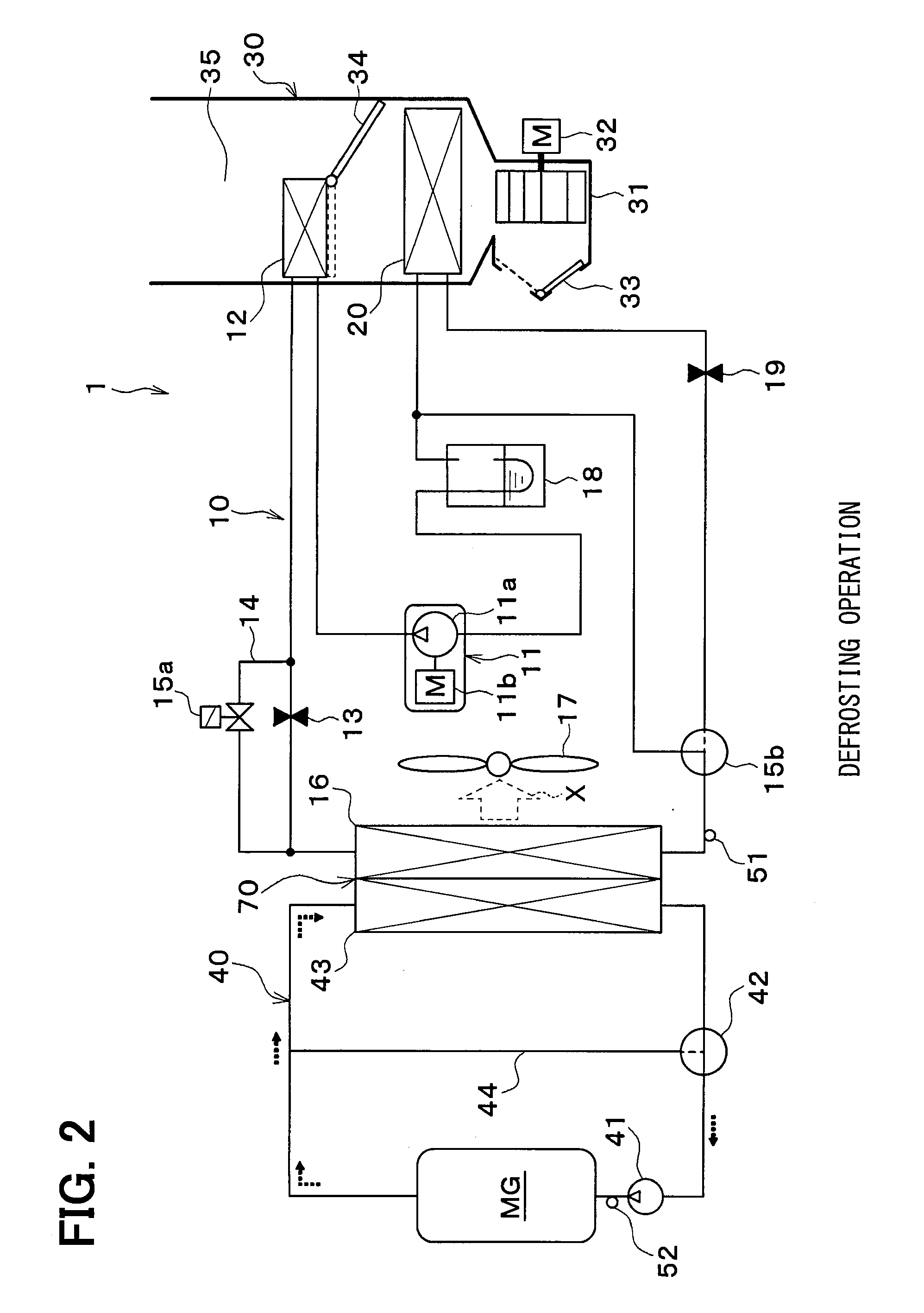
[0090]A first embodiment of the present disclosure will be described with reference to FIGS. 1 to 10. In the present embodiment, a heat exchanger 70 of the present disclosure is used for a heat pump cycle 10 of a vehicle air conditioner 1 that conditions a temperature of air blown in to a vehicle compartment. FIGS. 1 to 3 are general configuration diagrams showing the vehicle air conditioner 1 of the present first embodiment.

[0091]The vehicle air conditioner 1 is used for a hybrid vehicle that obtains a driving force for vehicle-running from an internal combustion engine (engine) and from a running electric motor MG.

[0092]The hybrid vehicle operates or stops the engine depending on a running load of the vehicle. The hybrid vehicle is capable of switching its running state, for example, between a running state, in which the driving force is obtained from both the engine and the running electric motor MG, and a running state, in which the engine is stopped and the driving force is obt...

second embodiment

[0224]Next, a second embodiment of the present disclosure will be described in reference to FIG. 11. The second embodiment is different from the first embodiment in shape of header tank 75. FIG. 11 is a perspective sectional diagram showing a heat exchanger 70 of the second embodiment.

[0225]As shown in FIG. 11, a header tank 75 of the heat exchanger 70 includes a header plate 751 to which both refrigerant tubes 16a and coolant tubes 43a are fixed, and a tank forming member 753. An upstream refrigerant space 733, an upstream coolant space 731 and a downstream refrigerant space 741 are formed inside the tank forming member 753 by fixing the tank forming member 753 to the header plate 751.

[0226]The upstream refrigerant space 733 and the upstream coolant space 731 are formed in an upstream tank portion 73. The upstream refrigerant space 733 collects or distributes refrigerant that flows through refrigerant tubes 16a of an upstream heat exchange portion 71. The upstream coolant space 731...

third embodiment

[0233]Next, a third embodiment of the present disclosure will be described with reference to FIG. 12. The third embodiment is different from the second embodiment in shape of header tank 75. FIG. 12 is a perspective sectional diagram showing a heat exchanger 70 of the third embodiment.

[0234]As shown in FIG. 12, a tank forming member 753 of a header tank 75 of the present embodiment is formed by extrusion molding. An upstream coolant space 731, an upstream refrigerant space 733 and a downstream refrigerant space 741 are provided inside the tank forming member 753. A communication space 76 is provided between the tank forming member 753 and a header plate 751, and refrigerant tubes 16a of an upstream heat exchange portion 71 communicates with refrigerant tubes 16a of a downstream heat exchange portion 72 through the communication space 76.

[0235]The tank forming member 753 includes a first communication hole 753a through which the upstream refrigerant space 733 communicates with the co...


PUM


Abstract

A heat exchanger includes a heat exchange portion in which at least tubes of refrigerant tubes or coolant tubes are stacked and at least one of refrigerant or coolant exchanges heat with air. An air passage is formed in a space formed between tubes of the refrigerant tubes and the coolant tubes which are adjacent to each other. An upstream heat exchange portion located on an upstream side in a flow direction of air and a downstream heat exchange portion located downstream of the upstream heat exchange portion in the flow direction of air are provided as the heat exchange portion. A ratio of the number of the refrigerant tubes to the total number of tubes of the upstream heat exchange portion is different from a ratio of the number of the refrigerant tubes to the total number of tubes of the downstream heat exchange portion.

Description

CROSS REFERENCE TO RELATED APPLICATION[0001]This application is based on and incorporates herein by reference Japanese Patent Applications No. 2011-82759 filed on 4 Apr. 2011, No. 2012-13061 filed on 25 Jan. 2012, and No. 2012-62935 filed on 20 Mar. 2012.TECHNICAL FIELD[0002]The present disclosure relates to a combined heat exchanger configured such that three kinds of fluids are capable of exchanging heat thereamong.BACKGROUND ART[0003]Conventionally, a combined heat exchanger is known, which is configured such that three kinds of fluids are capable of exchanging heat thereamong. For example, a heat exchanger disclosed in Patent Document 1 is a combined heat exchanger that is configured such that refrigerant of a refrigeration cycle and external air (outside air) are capable of exchanging heat therebetween and coolant which cools an engine and the outside air are capable of exchanging heat therebetween.[0004]Specifically, the heat exchanger of Patent Document 1 includes multiple tu...

Claims


Application Information

Patent Timeline
IPC IPC(8): F25B39/02
CPCF25B39/028B60K2001/003F28D1/0408F28D1/0435F28D1/05391F28D2021/0084F28D2021/0085F28D2021/0094F28D2021/0096F28F9/0204F28F9/0229F28F9/0278F28F2009/0287B60H1/32F28D1/04F28F1/32F28F9/02
Inventor KATOH, YOSHIKIINAGAKI, MITSUHARUSAITOU, MITSUYOSHISUGIMURA, RYOHEI
Owner DENSO CORP
Why Eureka
Try Eureka