
Front landing-gear well

Inactive Publication Date: 2014-09-04
AIRBUS OPERATIONS (SAS)
View PDF6 Cites 4 Cited by
  • Summary
  • Abstract
  • Description
  • Claims
  • Application Information

AI Technical Summary

Benefits of technology

The invention provides a way to transfer loads from a breaker strut to the aircraft's fuselage using a beam-shaped structural element. This helps to reinforce the strut and can reduce the weight of the removable covers on the roof of the landing gear well. The design also eliminates the need for the covers to resist the forces of the breaker strut and jack. Overall, this simplifies the load transfer system and improves the efficiency of the aircraft's design.

Problems solved by technology

The use of this material, particularly for the beam and the elements defining the landing gear well, results in a non-negligible mass saving.

Method used


Image

  • Front landing-gear well
  • Front landing-gear well
  • Front landing-gear well

Examples


Embodiment Construction

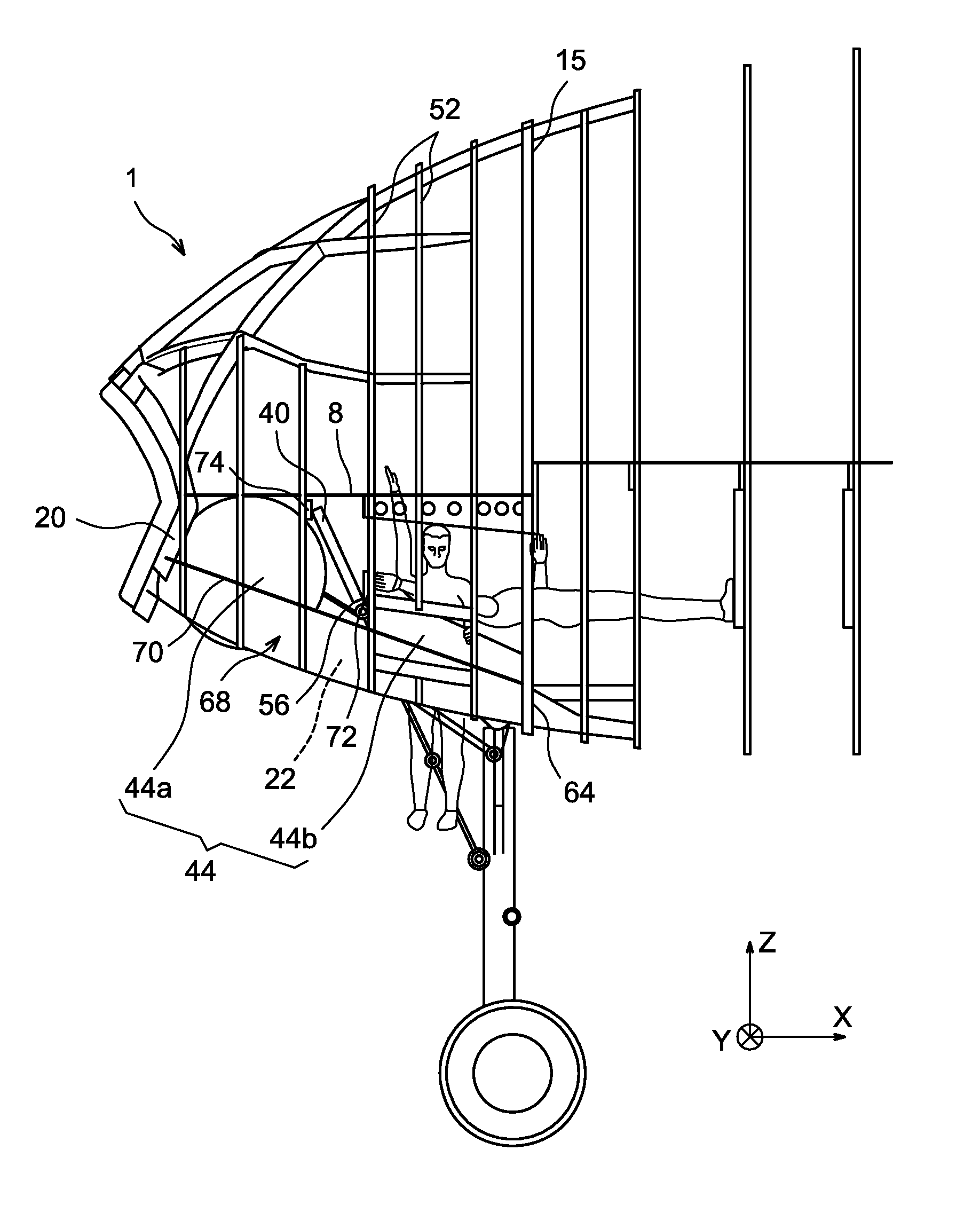
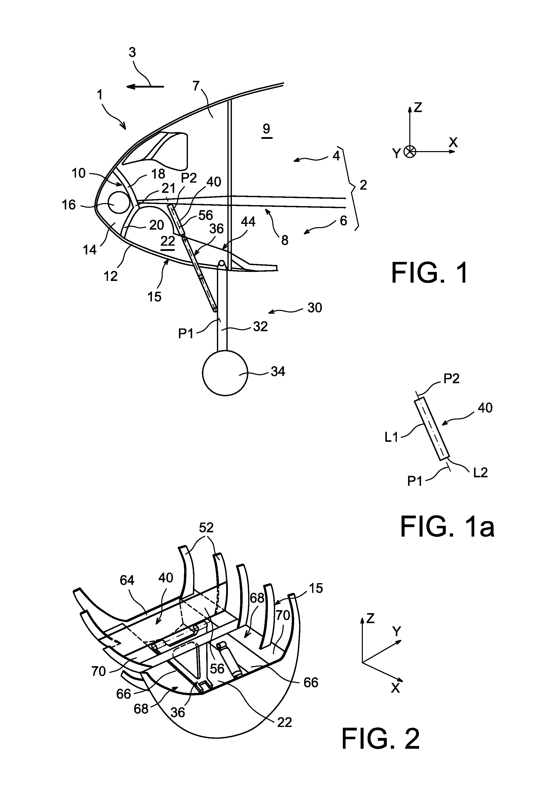
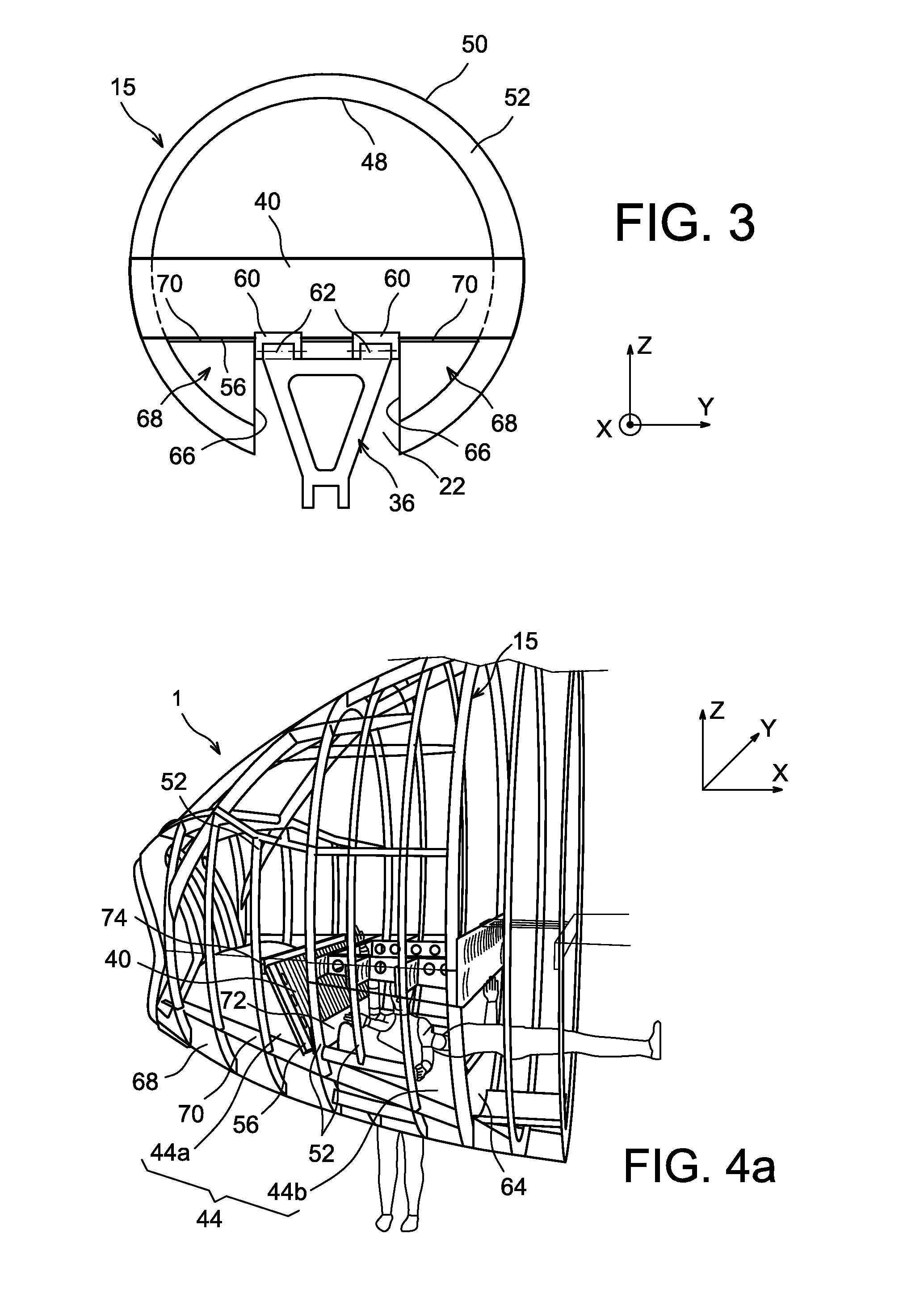
[0045]Throughout the following description, by convention X is the longitudinal direction of the aircraft, Y is the direction transverse to the aircraft and Z is the vertical direction or the height, these three directions X, Y and Z being mutually orthogonal.

[0046]Furthermore, the terms “forward” and “aft” should be considered relative to the direction of motion of the aircraft that occurs as a result of the thrust applied by the turbojets, this direction being shown diagrammatically by the arrow 3.

[0047]The forward part 1 comprises firstly a pressurized zone 2 in its aft most part within which there is a separation floor 8 between an upper pressurized compartment 4 usually dedicated to the transport of persons, and an underfloor pressurized compartment 6 usually dedicated to storage of technical equipment specific to the aircraft and / or to storage of the cargo. More precisely, the upper pressurized compartment 4 usually comprises, in the direction from the forward end towards the ...


PUM


Abstract

A forward part of an aircraft comprising a fuselage and a landing gear well housing a forward landing gear comprising a breaker strut designed to adopt an extended configuration when the landing gear is extended, configuration in which said breaker strut lies in a strut plane parallel to the transverse direction of the forward part. The forward part comprises a transverse beam resisting strut reactions located above the landing gear well and mounted on the fuselage at its two ends, the beam having a globally rectangular cross-section, in which the median plane parallel to the length of the rectangle is coincident with said strut plane.

Description

CROSS-REFERENCES TO RELATED APPLICATIONS[0001]This application claims the benefit of the French patent application No. 11 58802 filed on Sep. 30, 2011, the entire disclosures of which are incorporated herein by way of reference.BACKGROUND OF THE INVENTION[0002]This invention relates to a forward part of an aircraft, also called the nose cone, comprising a landing gear well housing a forward landing gear.[0003]The invention is applicable to all types of aircraft.[0004]Many developments have been made to aircraft nose cones to optimize its mass, volume, cost, safety, ease of fabrication, maintenance, etc. One example of such a nose cone is disclosed in documents FR 2 910 875 and U.S. Pat. No. 7,784,736.[0005]Despite the existence of many constructions, the environment of the nose cone landing gear well can still be optimized, particularly to distribute forces introduced by the front landing gear breaker strut.[0006]Normally, the landing gear well is made by means of stiffened panels f...

Claims


Application Information

Patent Timeline
IPC IPC(8): B64C1/14B64C25/04B64C25/10
CPCB64C1/14B64C25/04B64C25/10B64C1/061B64C1/10B64C1/36B64C25/14
Inventor GUERING, BERNARDDURAND, YVES
Owner AIRBUS OPERATIONS (SAS)
Learn More