Action control device, action control method, imaging device, and program

a technology of action control and imaging device, applied in the direction of exposure control, camera filters, instruments, etc., can solve the problems of deteriorating resolution sense, and achieve the effect of reducing focus lag

Active Publication Date: 2014-09-04
SONY CORP
View PDF4 Cites 14 Cited by
  • Summary
  • Abstract
  • Description
  • Claims
  • Application Information

AI Technical Summary

Benefits of technology

[0021]According to the present technology, it is possible to reduce a focus lag.

Problems solved by technology

In recent years, in the field of compact digital cameras, as the density of pixels of an image sensor increases, there are cases in which a sense of resolution deteriorates due to the influence of a small aperture blur.

Method used


Image

  • Action control device, action control method, imaging device, and program
  • Action control device, action control method, imaging device, and program
  • Action control device, action control method, imaging device, and program

Examples


first embodiment

1. First Embodiment

Exemplary Configuration of Imaging Device According to First Embodiment of Present Technology

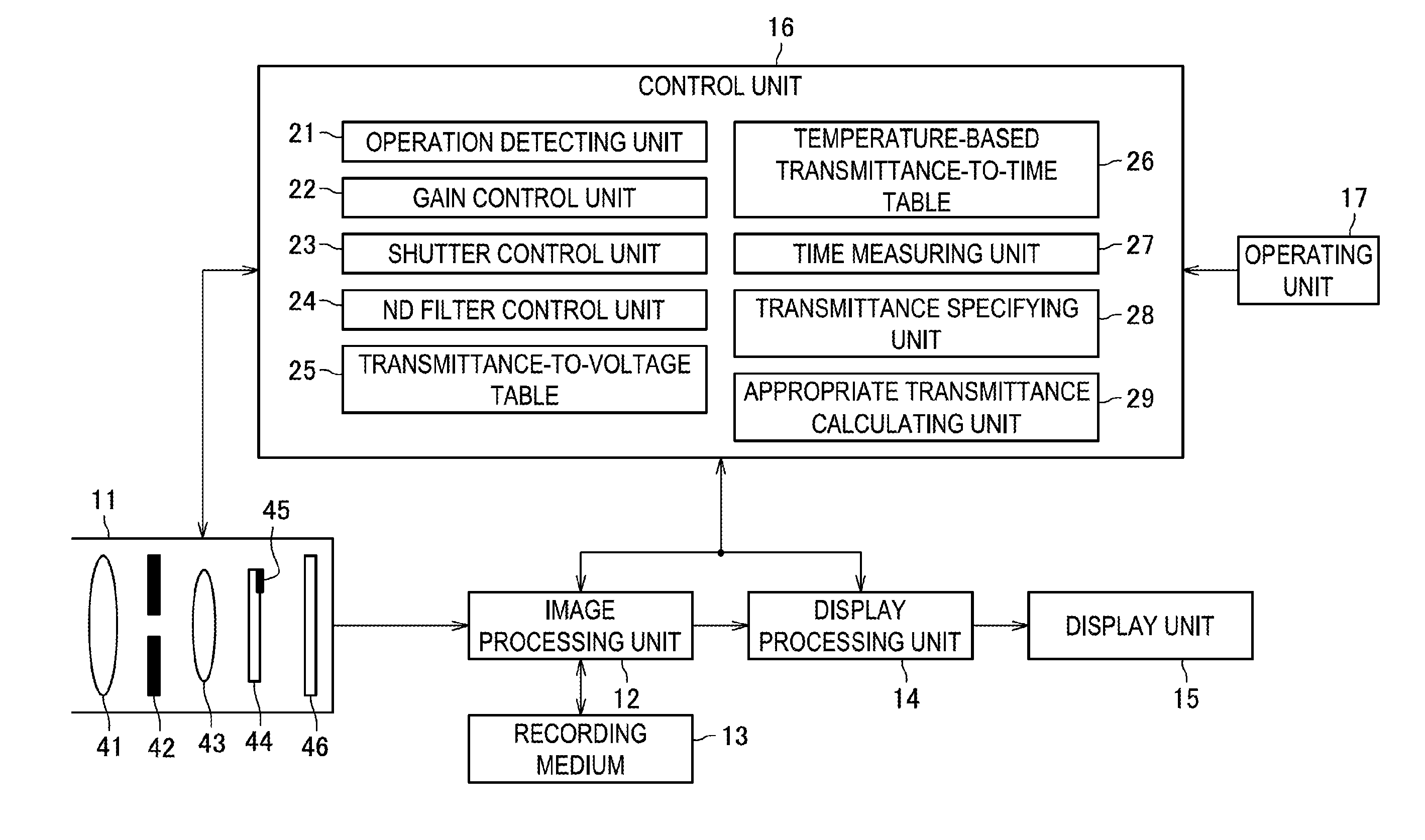
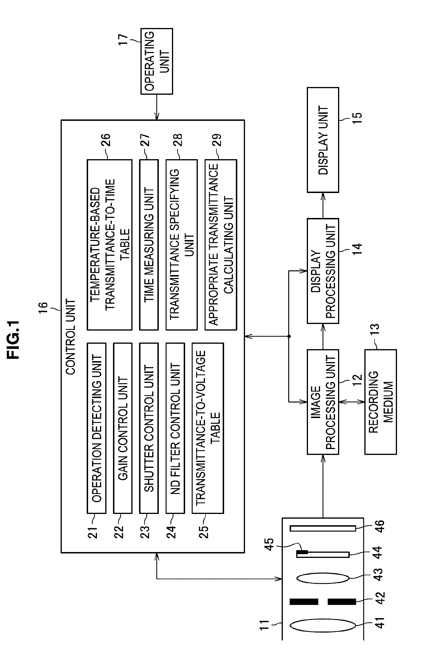
[0034]FIG. 1 is a diagram for describing an exemplary configuration of an imaging device according to a first embodiment of the present technology. The imaging device of FIG. 1 includes a lens barrel 11, an image processing unit 12, a recording medium 13, a display processing unit 14, a display unit 15, a control unit 16, and an operating unit 17, and causes an image imaged by an imaging element 46 installed in the lens barrel 11 to be recorded in the recording medium 13 or to be displayed on the display unit 15. More specifically, when a half push operation representing imaging preparation is performed on the operating unit 17 including a shutter button or the like, the control unit 16 controls the lens barrel 11 such that a focus is controlled. Then, when a full push operation representing an imaging instruction is performed on the operating unit 17 including the shutter...

second embodiment

2. Second Embodiment

Exemplary Configuration of Imaging Device According to Second Embodiment of Present Technology

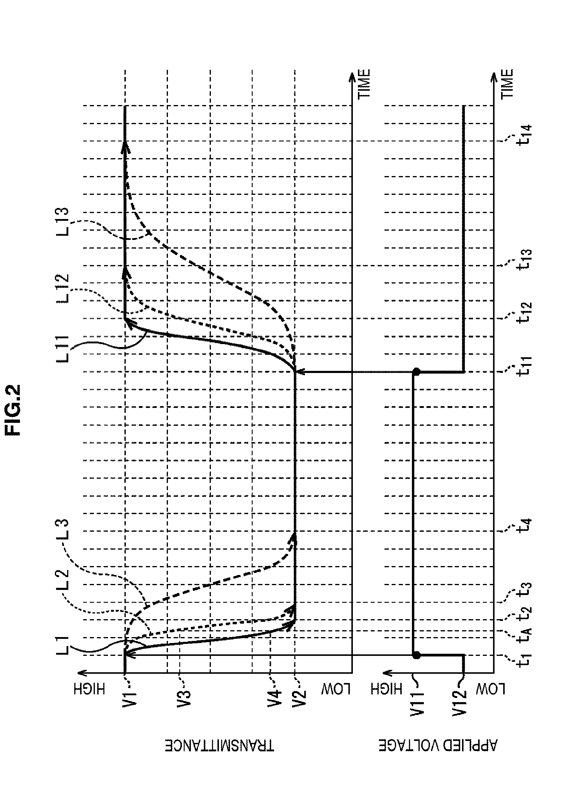
[0067]The above description has been made in connection with the example in which the transmittance is specified at a timing at which the half push operation is performed based on an elapsed time from a timing at which an applied voltage is applied to the liquid crystal ND filter and the temperature of the liquid crystal ND filter with reference to the transmittance-to-time table, and a gain and a shutter speed for adjusting an applied voltage for maintaining the specified transmittance and a difference with a target transmittance, that is, a difference with brightness to be adjusted by the liquid crystal ND filter, are calculated. However, as the transmittance at the timing at which the half push operation is performed, the transmittance of the liquid crystal ND filter may be measured at the corresponding timing and used.

[0068]FIG. 7 illustrates an exemplary configurati...


PUM

PropertyMeasurementUnit
transmittanceaaaaaaaaaa
transmittance calculatingaaaaaaaaaa
temperatureaaaaaaaaaa

Abstract

According to the first aspect of the present technology, there is provided an action control device, including a transmittance specifying unit configured to specify a transmittance of a variable-transmittance neutral density (ND) filter having a transmittance that varies according to an applied voltage, and an applied voltage control unit configured to control a voltage to be applied to the variable-transmittance ND filter such that the transmittance specified by the transmittance specifying unit is obtained. The applied voltage control unit controls the voltage to be applied to the variable-transmittance ND filter such that the transmittance of the variable-transmittance ND filter specified by the transmittance specifying unit is maintained at a timing at which an imaging preparation instruction or an imaging instruction is given.

Description

TECHNICAL FIELD[0001]The present technology relates to an action control device, an action control method, an imaging device, and a program, and more particularly to an action control device, an action control method, an imaging device, and a program which are capable of reducing a focus lag.BACKGROUND ART[0002]In recent years, in the field of compact digital cameras, as the density of pixels of an image sensor increases, there are cases in which a sense of resolution deteriorates due to the influence of a small aperture blur.[0003]In this regard, employment of a neutral density (ND) filter (variable-transmittance ND filter) that implements a desired transmittance without an aperture being changed by an applied voltage has been studied. Among ND filters, for example, a liquid crystal ND filter is used to reduce a drastic change in exposure and thus reduce an observer's fatigue by changing a transmittance when a light quantity drastically changes in an eyepiece image at the time of s...

Claims


Application Information

Patent Timeline
Patent Type & Authority Applications(United States)
IPC IPC(8): G03B7/00G03B7/08H04N5/232G02F1/133H04N5/225H04N5/238G02F1/01G03B7/22
CPCG03B7/00G02F1/0121G03B7/0805H04N5/23212G02F1/13318H04N5/225H04N5/238G03B7/22G03B9/02G03B11/00H04N23/55H04N23/75
Inventor TAKAGI, YOSHIMITSU
Owner SONY CORP
Why Eureka
Try Eureka