Structured illumination ophthalmoscope

a structure illumination and ophthalmoscope technology, applied in the field of high resolution microscopy, can solve the problems of not being able to diagnose extrinsically (non-invasively) with conventional methods, the spatial resolution of conventional non-invasive imaging methods is not sufficient to analyse these fine fluorescent structures directly at the patient, and many disturbing effects, so as to reduce scattering and diffraction in regions outside the focus plane, less costly, and less critical

Active Publication Date:
View PDF1 Cites 10 Cited by
  • Summary
  • Abstract
  • Description
  • Claims
  • Application Information

AI Technical Summary

Benefits of technology

[0018]Moreover, according to an aspect, the eye is subjected to a wide-field illumination. Thus, it is not necessary to subject the eye to light with high illumination intensity and / or energy densities which might degrade or damage it. Further, disturbing influences of auto-fluorescence, scattering and diffraction in regions outside the focus plane can be reduced.
[0019]Another advantage of the ophthalmoscope described herein may be that low-cost pattern generation devices (for example micro liquid crystal displays) can be used for structuring / patterning the illumination light illuminating the eye. Accordingly, an ophthalmoscope with a less costly, less critical and more stable optical setup as compared to prior art solutions may be realized.
[0020]A further advantage may be the reduction in the requirements for the stability of the optical set up of the ophthalmoscope and in particular the requirements for stability of the illumination during the acquisition of the series of images of the observed retinal region of the eye. This simplifies the optical set up of the ophthalmoscope, while improving its resolution.
[0021]The use of the structured or patterned illumination may reduce the influence of disturbing effects due to auto-fluorescence, diffraction and scattering outside the object plane, thereby obtaining a significant improvement of resolution and contrast.
[0022]In addition, the method for non-invasive fluorescence observations of an eyeground and the corresponding ophthalmoscope according to an aspect may be efficiently combined with other microscopic techniques, for example with localization microscopy and / or fluorescence tomography and / or other 3D techniques. Such a combined application is particularly suitable in cases where an eye tissue has to be removed for medical reasons, or in cases of experimental studies using animal models.

Problems solved by technology

Diseases of the eye fundus (e.g. the age-related macular degeneration) are frequently accompanied with microscopic physiological changes, which cannot be diagnosed extrinsically (non-invasively) with conventional methods.
Due to the distance between the fundus and the eye-lens, the spatial resolution of conventional non-invasive imaging methods is not sufficient to analyse these fine fluorescent structures directly at the patient.
Furthermore, there are many disturbing effects due to auto-fluorescence, diffraction and scattering outside the object plane.
Conventional wide-field fundus cameras suffer from a low contrast.
However, the use of adaptive optics is complex and cost-intensive.
Therefore, due to temporary high local thermal exposures an application in connection with humans, particularly in ophthalmoscopy, is problematic.
Since the fundamental requirements for light hazard protection (ISO 15004-2:2007) have to be met, only relatively small energy densities are allowed in connection with ophthalmic instruments, which may lead to a low signal-to-noise relation.
An expensive laser system and a relatively complex arrangement are further drawbacks of the two-photon technique.
Moreover, another difficulty frequently occurring in the field of ophthalmology is that a healthy eye, which is not fixed, permanently carries out eye movements, even when the eye is kept subjectively still.
Such movements are usually considered to be obstructive for imaging the fundus.

Method used


Image

  • Structured illumination ophthalmoscope
  • Structured illumination ophthalmoscope
  • Structured illumination ophthalmoscope

Examples


Embodiment Construction

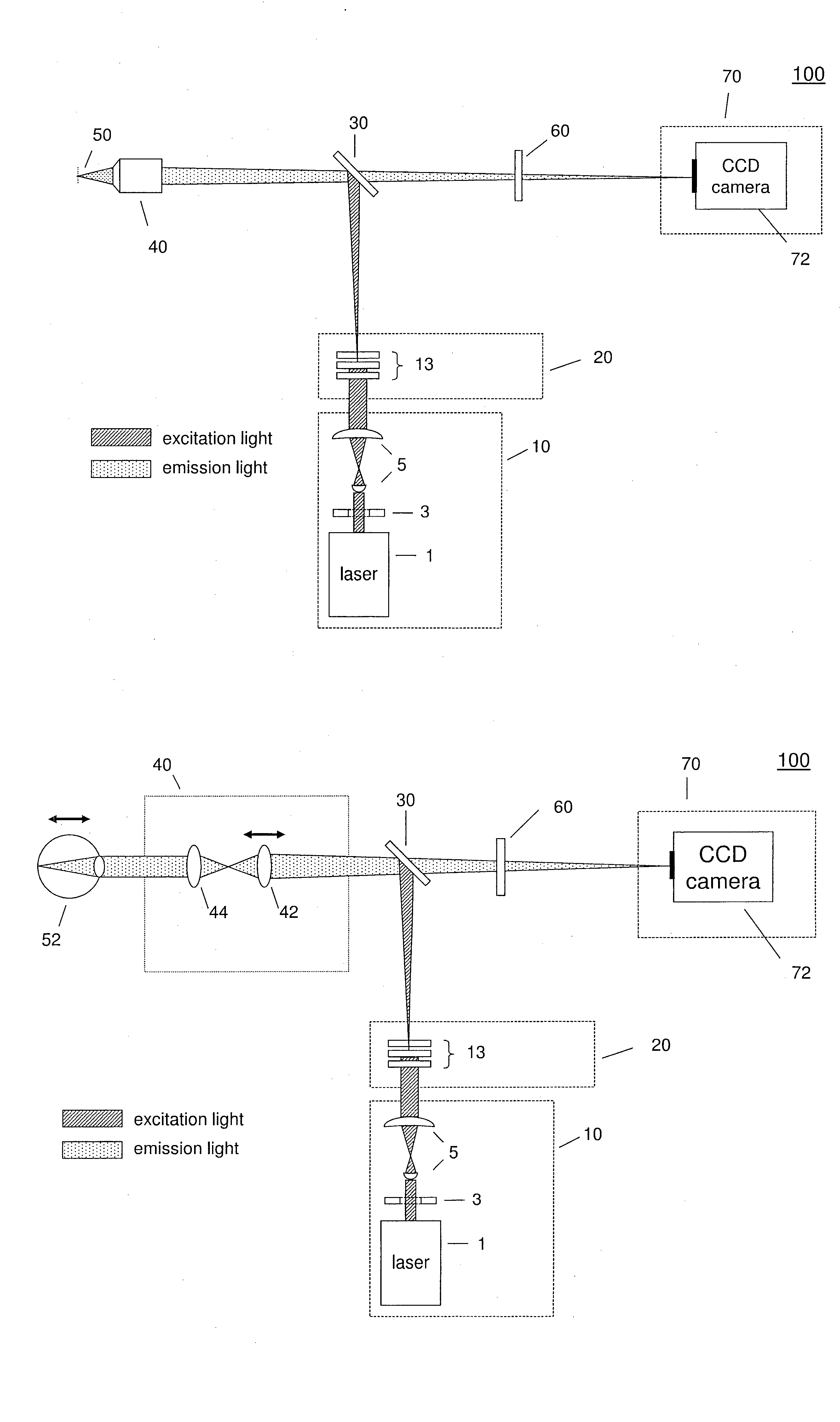
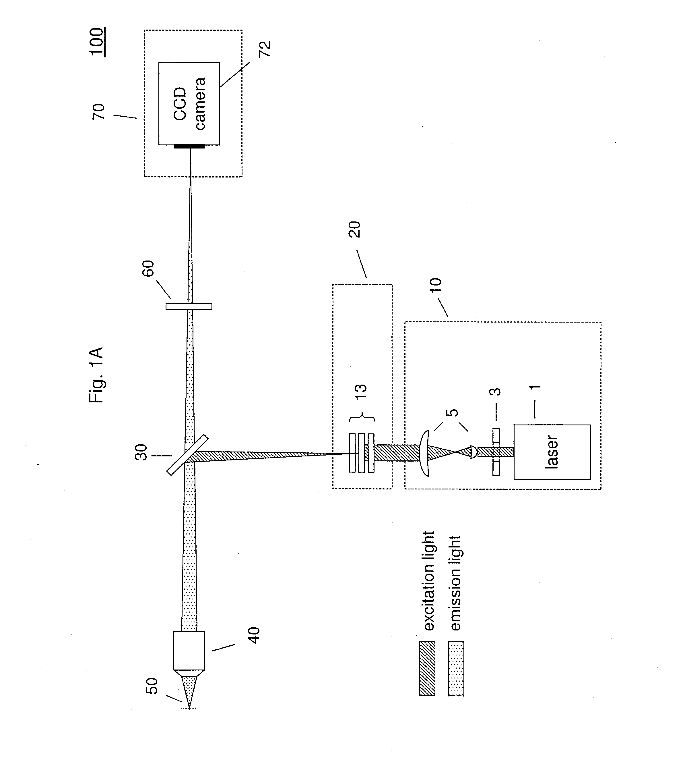
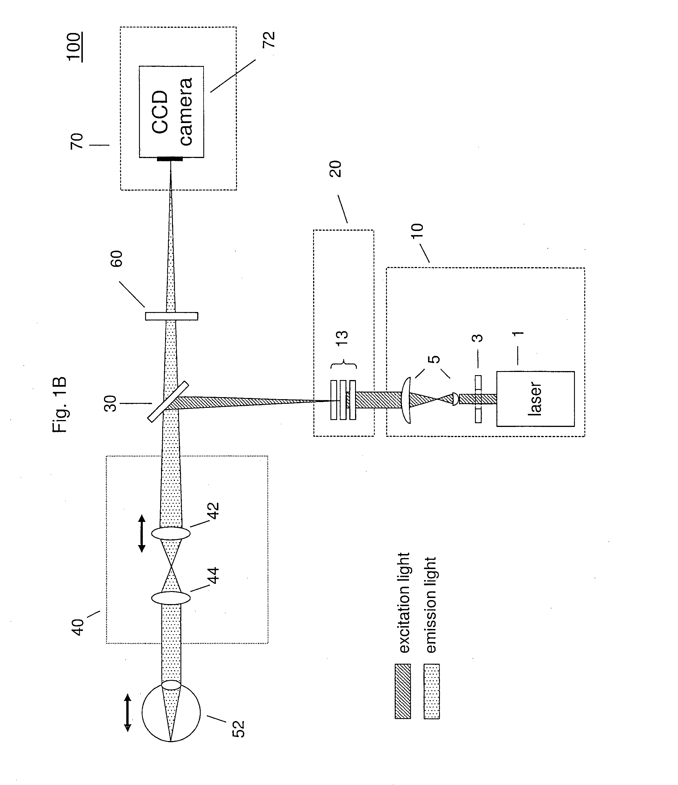
[0034]According to an example, there is provided a method for non-invasive observations of a fundus. The method includes illuminating a retinal region of an eye by projecting an illumination pattern of illumination light onto the retinal region of the eye and detecting at least a portion of fluorescent light emitted from the retinal region of the eye and / or detecting at least a portion of illumination light reflected from the retinal region of the eye, thereby capturing a series of raw images of the retinal region of the eye at a plurality of different relative positions of the retinal region of the eye with respect to the illumination pattern projected onto the retinal region of the eye. Between the capturing of at least two images of the series (for example between the capturing of each two consecutive images of the series) the relative position of the retinal region of the eye with respect to the illumination pattern projected onto the retinal region of the eye is shifted in a no...


PUM


Abstract

A method for non-invasive observations of a fundus using an ophthalmoscope is provided. The method includes illuminating a retinal region of an eye by projecting an illumination pattern of illumination light onto the retinal region, at least one of detecting a portion of fluorescent light emitted from the retinal region and detecting a portion of illumination light reflected from the retinal region, thereby capturing a series of images of the retinal region at a plurality of different relative positions of the retinal region with respect to the illumination pattern projected onto the retinal region, wherein between the capturing of at least two images of the series the relative position of the retinal region with respect to the illumination pattern projected onto the retinal region is shifted in a non-controlled manner, and processing the captured images to extract a sub-resolution image of the retinal region.

Description

CROSS REFERENCE TO RELATED APPLICATIONS[0001]This application is a National Stage Entry of PCT / EP2013 / 002895 filed Sep. 26, 2013, which claims priority from European Patent Application No. EP 12006779.8 filed Sep. 28, 2012, both of which are incorporated herein in their entirety.BACKGROUND[0002]The present invention relates to a high resolution microscopy for the use in ophthalmology.[0003]In particular, the present invention relates to a method, an apparatus (an ophthalmoscope), a computer implemented method and a computer program product for non-invasive observations of the fundus of an eye (eyeground).[0004]Diseases of the eye fundus (e.g. the age-related macular degeneration) are frequently accompanied with microscopic physiological changes, which cannot be diagnosed extrinsically (non-invasively) with conventional methods. Thus for example, age-related macular degeneration is accompanied with the deposit of fluorescent pigments in the retinal pigment epithelium (RPE).[0005]Inve...

Claims


Application Information

Patent Timeline
Patent Type & Authority Applications(United States)
IPC IPC(8): A61B3/12A61B3/00
CPCA61B3/0008A61B3/12
Inventor CREMER, CHRISTOPHBEST, GERRITAMBERGER, ROMANHEINTZMANN, RAINERDITHMAR, STEFANACH, THOMAS
Why Eureka
Try Eureka