Light source device and projector
- Summary
- Abstract
- Description
- Claims
- Application Information
AI Technical Summary
Benefits of technology
Problems solved by technology
Method used
Image
Examples
first embodiment
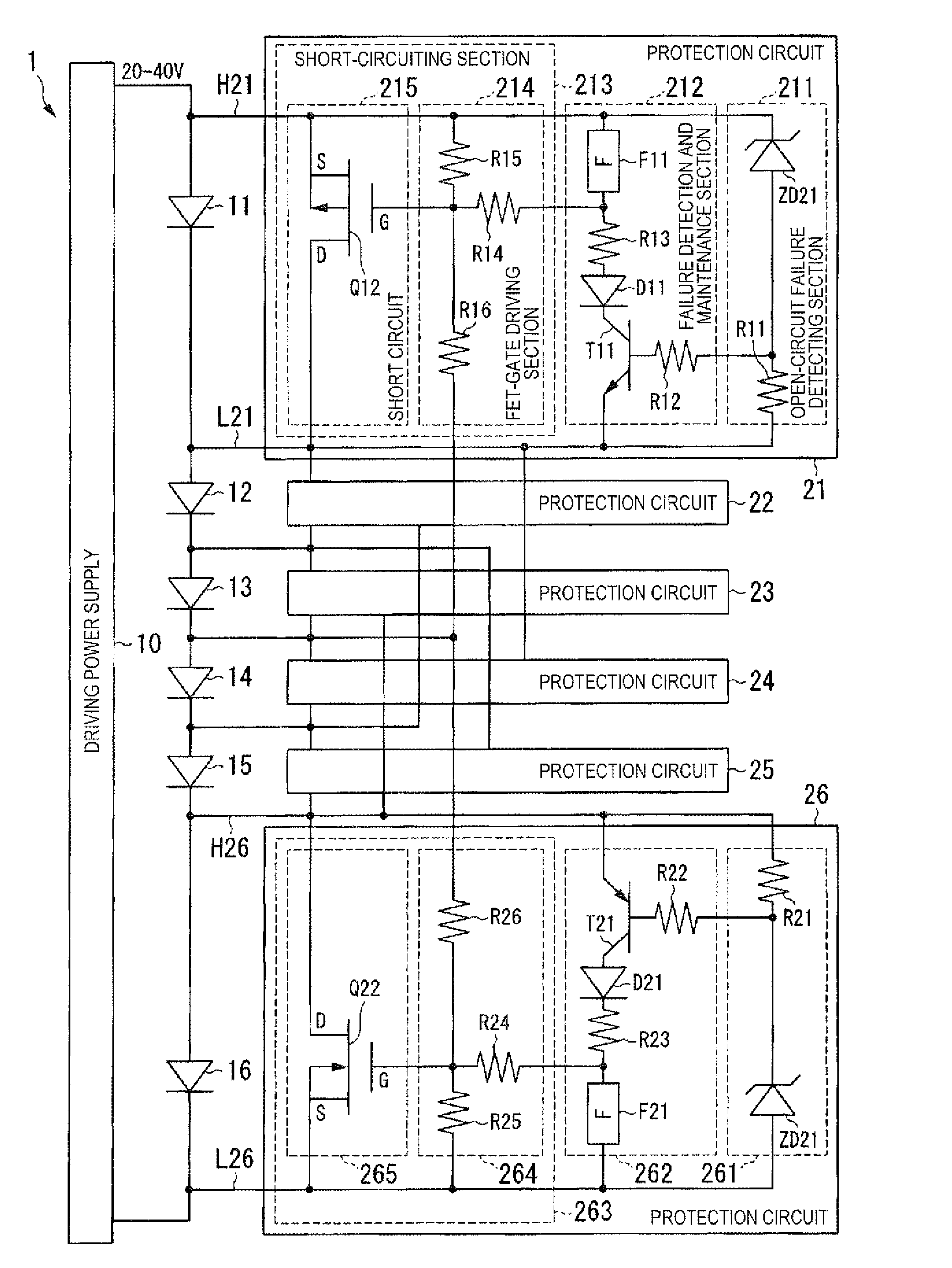
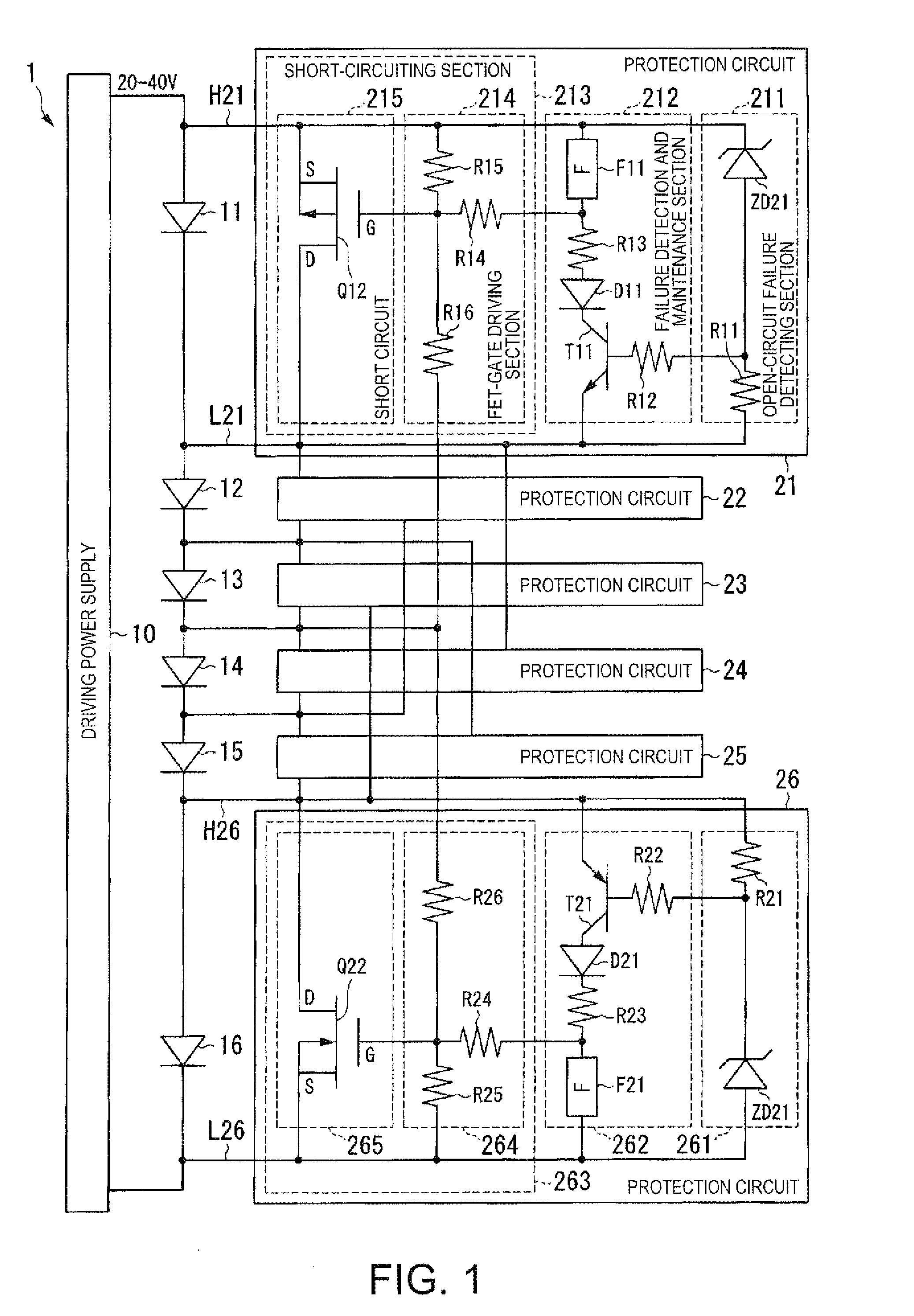
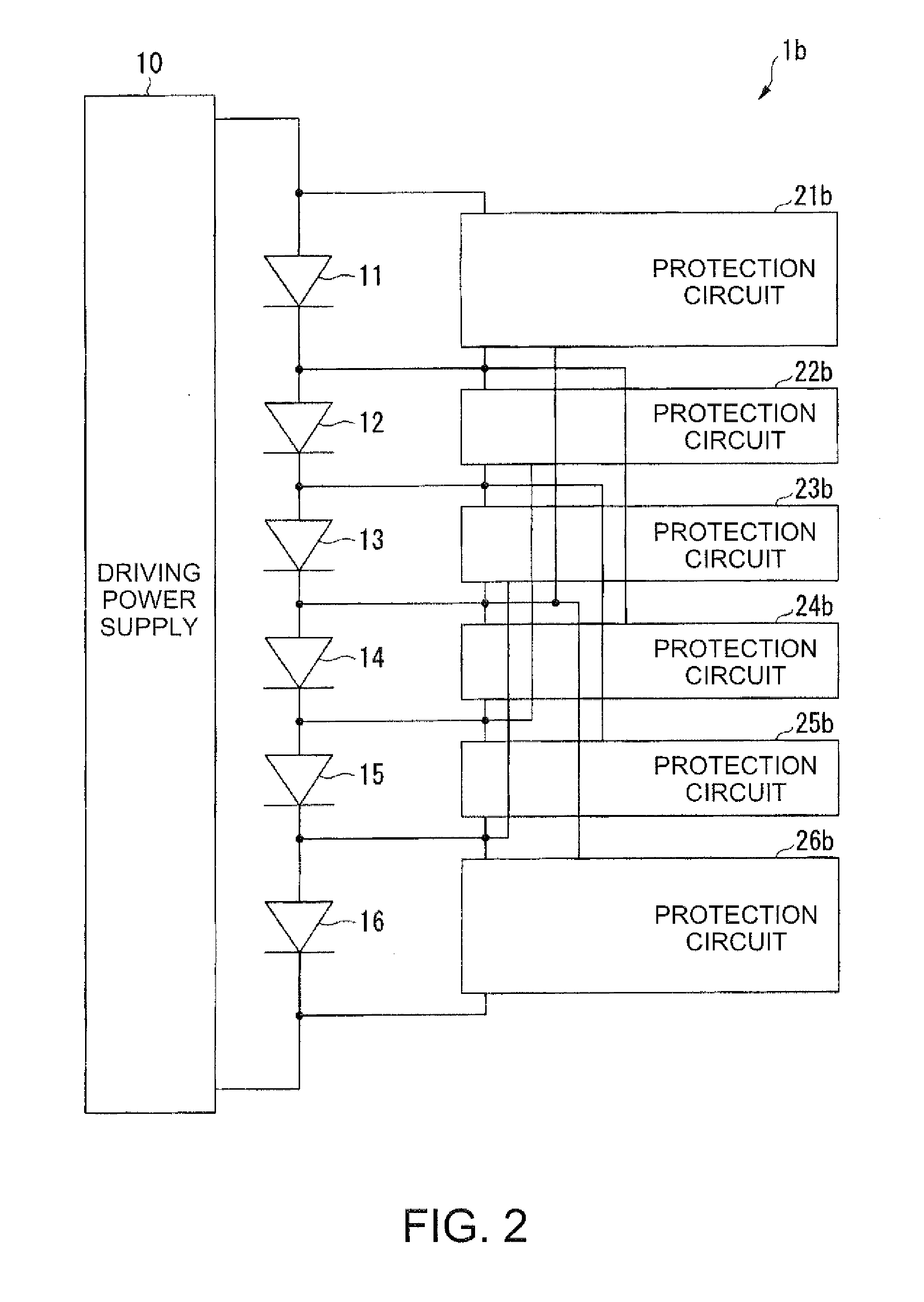
[0035]Embodiments of the invention are explained in detail below with reference to the drawings. FIG. 1 is a schematic block diagram showing the configuration of a light source device 1 in a first embodiment. The light source device 1 includes a driving power supply 10, six light emitting devices 11 to 16, and six protection circuits 21 to 26. The light emitting devices 11 to 16 are connected in series in order. The light emitting devices 11 to 16 are, for example, light emitting diodes. When a predetermined voltage (e.g., a voltage equal to or higher than 3.3 V and lower than 5.0 V) is applied to anodes of the light emitting devices 11 to 16, the light emitting devices 11 to 16 emit light. An anode of the light emitting device 11 is connected to the driving power supply 10 and a cathode of the light emitting device 11 is connected to an anode of the light emitting device 12. Similarly, the anode of the light emitting device 12 is connected to the cathode of the light emitting devic...
second embodiment
[0070]A second embodiment is explained. In the first embodiment, when an electric current is fed to the fuse F11, a resistance value of the fuse 111 rises according to a temperature rise of the fuse F11. A voltage across both ends of the fuse rises according to the rise in the resistance value. Consequently, a gate voltage of the pMOS transistor Q12 drops and the pMOS transistor Q12 starts to change to the ON state. Therefore, an electric current flows between the source and the drain of the pMOS transistor Q12 and the electric current flowing to the fuse F11 decreases.
[0071]On the other hand, in the second embodiment, the fuse F11 is connected to the gate of the pMOS transistor Q12 via two transistors. Consequently, since the pMOS transistor Q12 is in the OFF state until the fuse F11 is completely fused, the electric current flowing to the fuse F11 does not decrease until the fuse F11 is completely fused. Therefore, it is possible to prevent time until the fuse F11 is fused from be...
third embodiment
[0094]A third embodiment is explained. In the first embodiment and the second embodiment, since the driving power supply 10 performs constant current control, a predetermined voltage (e.g., 5 V) can be applied to the fuse at most. On the other hand, in a protection circuit in the third embodiment, since a voltage applied to a fuse is set to a voltage (e.g., 15 V) three times as high as the voltage in the first embodiment, even if the resistance of the fuse rises and a voltage applied to both ends of the fuse rises to about 10 V at an instance when the fuse is cut, it is possible to still feed an electric current equal to or larger than a predetermined current (e.g. 2 A) to the fuse. Consequently, since a large current can be continuously fed even if the resistance of the fuse rises, it is possible to more surely fuse the fuse.
[0095]The configuration of a light source device 1c in the third embodiment is explained below. FIG. 5 is a schematic block diagram showing the configuration o...
PUM
 Abstract
Description
Claims
Application Information
 - R&D
- Intellectual Property
- Life Sciences
- Materials
- Tech Scout
- Unparalleled Data Quality
- Higher Quality Content
- 60% Fewer Hallucinations
Browse by: Latest US Patents, China's latest patents, Technical Efficacy Thesaurus, Application Domain, Technology Topic, Popular Technical Reports.
© 2025 PatSnap. All rights reserved.Legal|Privacy policy|Modern Slavery Act Transparency Statement|Sitemap|About US| Contact US: help@patsnap.com


