Bridge span replacement system

a bridge span and replacement system technology, applied in bridges, hoisting equipment, instruments, etc., can solve problems such as needing replacement, weakening corrosion, and developing faults

Inactive Publication Date: 2014-09-11
WESTERN MECHANICAL ELECTRICAL MILLWRIGHT SERVICES
View PDF4 Cites 21 Cited by
  • Summary
  • Abstract
  • Description
  • Claims
  • Application Information

AI Technical Summary

Benefits of technology

[0065]Optionally, the vertical support and lift system is adapted to be used with or directly operatively associated with (e.g. secured to) to an overhang ground-support system for example overhang portions of a ground support structure. The term “ground support structure” is used to any structure used to introduce a load-bearing support feature and / or a stability feature e.g. in order to enhance or form the first, second or third ground locations. The ground support structure is optionally operatively associated with an alignment system, for example a vertical and / or lateral alignment system, optionally including an alignment means for aligning the ground engaging portion of the gantry legs with overhang portions of the overhang ground support system, for example for aligning connection portions that enable the ground engaging portions to be connected to the overhang portions or the overhang portions to be connected to ground support portions of the overhang ground support system. The alignment means may be a vertical alignment means, for example a projecting abutment portion or other stop means to gauge or define stop positions when lowering the leg portions from off the pre-installation conveyance system, for example, so that the overhang portions of the overhang ground support system are urged to be arrested into alignment with the ground support portions of the overhang ground support system. Thus, the overhang ground support system defines or provides first ground support locations for supporting the ground engaging vertical support and lift system. Optionally, the ground engaging portions of the leg portions are pre-attached to and include the overhang portions of the ground support structure. In a methodological aspect the method of the invention optionally includes, preliminary to effecting a gantry installation, a preliminary ground-support preparation step optionally including the step of installing the ground support portions of an overhang ground support system e.g. in the form a ground support structure like a beam. Optionally, the alignment system includes accurate positioning the rail carts on the train track (x axis), accurate positioning of the gantry assembly on the rail carts (y axis) along with lateral play in mating portions of the gantry leg and the ground engaging (e.g. shoe or foot) portion (the foot portion is pinned to the leg portion in a manner in which provides play in the Y axis) and controlled finally lowering of the gantry legs (z axis) aided by a vertical alignment system in the form of an vertical alignment means e.g. a laterally projecting abutment portion.
[0087]Optionally, as described above, the outrigger portion and leg portions of at least one vertical support assembly are rotationally mounted, for example, with respect to positionally-fixed portions of the gantry connection portion, for movement about a vertical axis perpendicular to the longitudinal axis of the gantry between a stowed position and a laterally extended installation position. Optionally, each vertical support assembly comprises an outrigger portion and two leg portions, the leg portions adapted to be contracted by the vertical support and lift system to occupy a compact configuration which provides suitable ground clearance in the stowed position.
[0098]A connector is optionally configured so that straps move transversely with respect to the longitudinal axis of the gantry to increase transverse play of the straps with respect to the ends of the spreader structure or the bridge span.

Problems solved by technology

Bridge spans can last for decades but increasingly undergo weakening corrosion, develop faults and eventually need to be replaced.
Accordingly, replacing a bridge span can pose considerable challenges.
For example, a train bridge may be located in areas that are difficult to access with cranes and other types of conventional heavy equipment of the type needed to replace a 150 ton bridge span.
However, access from beneath a bridge is only possible where the underlying area is accessible by large vehicles or navigable by large floating vessels.
Furthermore, a site of span replacement may be an environmentally sensitive area that would be damaged by bringing in conventional or specialized equipment.
Furthermore, replacing a bridge span may interrupt train traffic for a considerable period of time.
The down-time costs railway companies and the industries they service large sums in lost time and / or revenues.

Method used


Image

  • Bridge span replacement system
  • Bridge span replacement system
  • Bridge span replacement system

Examples


example

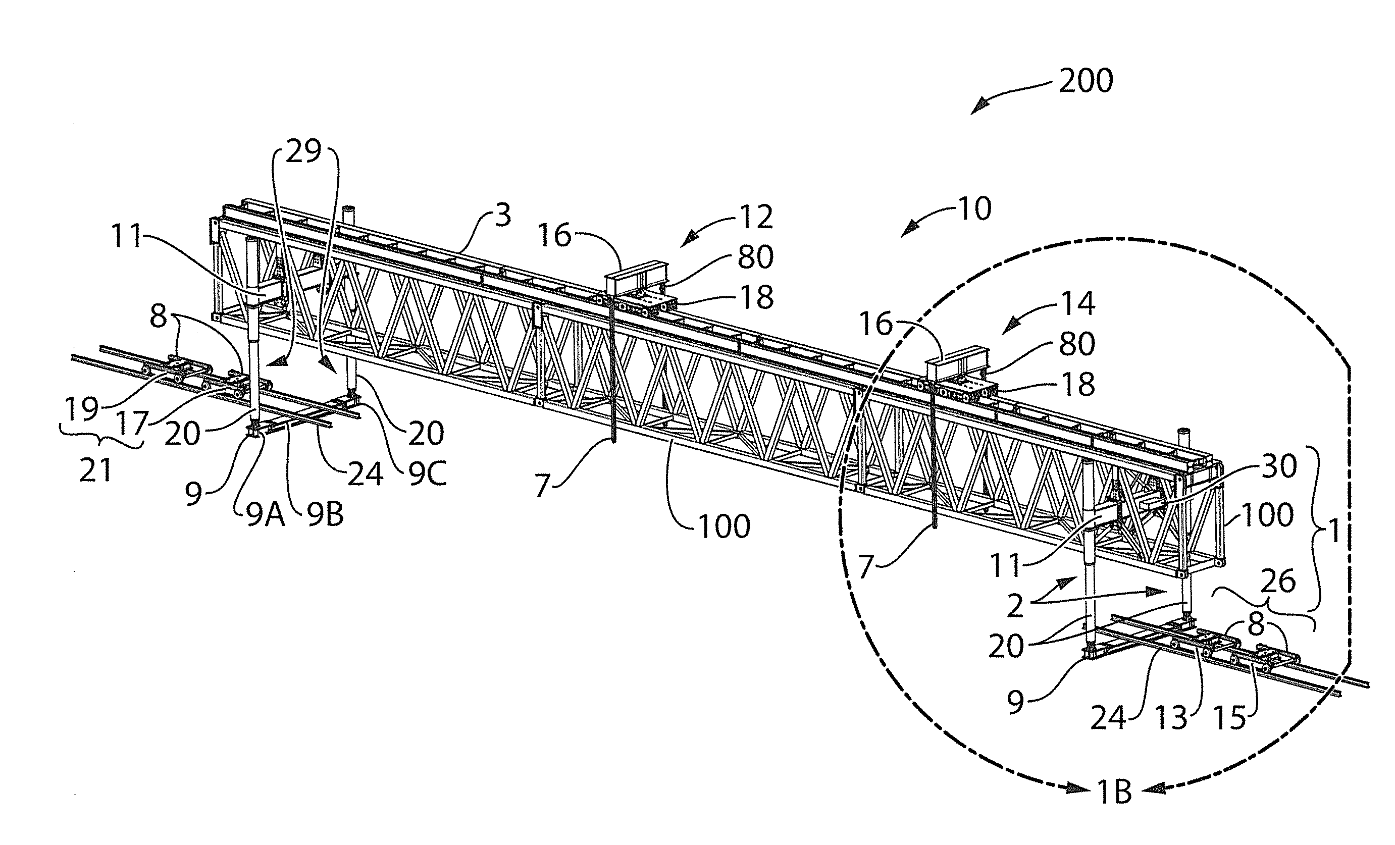
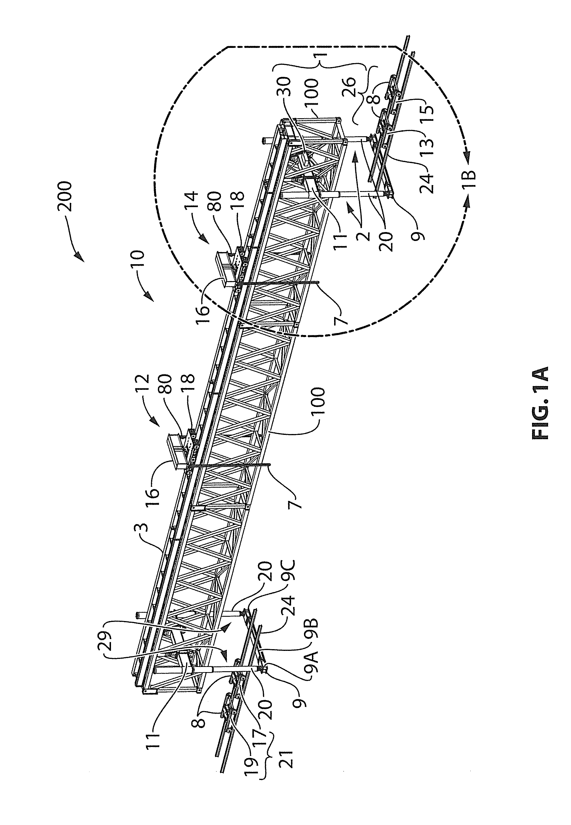
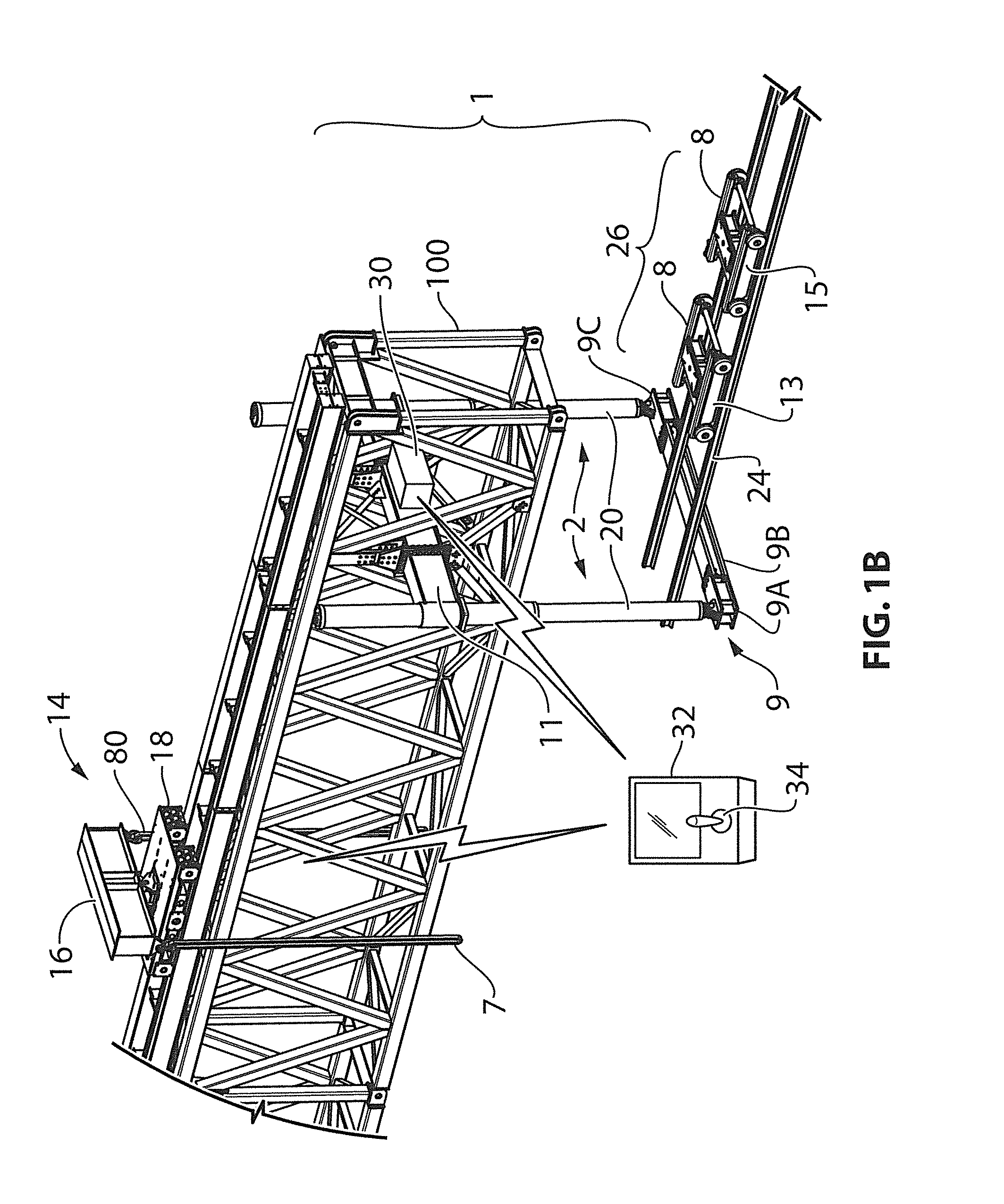
[0460]A gantry may be approximately 150 feet in length). Railway clearances depending on the location may be approximately 14 feet wide and the lateral dimension of the gantry assembly with the outrigger portion and gantry legs positioned in a stowed position may be approximately 11-11.5 feet and may be carried on a rail car having a conventional support deck of approximately 10 feet in width. A bridge span transported to a gantry assembly installation may have a lateral footprint which may be approximately a foot shorter than the maximum lateral railway clearance. When the outrigger and leg portions of the vertical support assemblies are in an installation position they may provide a 9 inch plus clearance on either side the bridge span, or a total clearance of approximately 14 to 15 feet (e.g. 14.5 feet), the centers of gantry legs laterally spanning approximately 15 to 16 feet (e.g. 15.5 feet) and supported on support beams (alternatively termed tie beams) of approximately 16 feet...


PUM


Abstract

A vertically-adjustable gantry assembly installation adapted for removal or placement of a train bridge-span of the type which spans and is supported by two piers, comprises a gantry assembly positioned on load-bearing first ground-support locations, the gantry assembly comprising a gantry and a ground-engaging vertical support and lift system, the vertical support and lift system adapted for supporting a combined weight of the gantry and a bridge span in at least one operational vertical position above respective bridge span support-surfaces of the piers including a position corresponding to a disembarking plane in which the leg portions are extended from a stowed position to an extent at least sufficient for the gantry assembly to self-liftoff the pre-installation conveyance system onto the first ground-support locations to effect the gantry assembly installation.

Description

CROSS-REFERENCE TO RELATED APPLICATIONS[0001]This application is a continuation of co-pending application Ser. No. 13 / 787,461, filed on Mar. 6, 2013, the disclosure of which is incorporated herein by reference in its entirety.FIELD OF THE INVENTION[0002]The present invention relates to a method, system, apparatus and installation for replacing a train bridge span.BACKGROUND OF THE INVENTION[0003]Trains that travel through urban and rural areas need to cross over roads, hilly terrain and terrain interrupted by other natural vehicle barriers including bodies of water. Train tracks crossing a train bridge are often supported on a replaceable bridge span supported by two piers. Bridge spans can last for decades but increasingly undergo weakening corrosion, develop faults and eventually need to be replaced.[0004]Bridge spans can weigh, on average, as much as 150 tons, and can be as long as 30 meters so that they span two supporting piers. Accordingly, replacing a bridge span can pose con...

Claims


Application Information

Patent Timeline
Patent Type & Authority Applications(United States)
IPC IPC(8): E01D22/00B66C19/00B66C19/02
CPCE01D22/00B66C19/005B66C19/02E01D21/06G06F9/45558G06F9/4856G06F2009/45562G06F2009/4557H04L67/1001H04L67/133G06F9/5027G06F9/5088G06F11/1458H04L67/1095H04L67/1097B66C5/04B66C13/04B66C17/20B66C19/002
Inventor CARNEY, MARKDOUCET, ROBELISSES, LARRY
Owner WESTERN MECHANICAL ELECTRICAL MILLWRIGHT SERVICES
Why Eureka
Try Eureka