Mass spectrometer

a mass spectrometer and mass spectrometer technology, applied in the field of mass spectrometers, can solve the problems of reducing the transmission efficiency of ions and lowering the maintenance efficiency, and achieve the effect of improving the detection sensitivity and improving the ion transmission efficiency

Active Publication Date: 2014-09-11
SHIMADZU CORP
View PDF13 Cites 3 Cited by
  • Summary
  • Abstract
  • Description
  • Claims
  • Application Information

AI Technical Summary

Benefits of technology

[0025]In the mass spectrometer according to the present invention, the ion-confining effect of the two radio-frequency electric fields respectively created by the front-stage and rear-stage ion guides seamlessly continues at the opening of the ion lens or the aperture plate and thereby improves the ion transmission efficiency. As a result, a larger amount of ions will be subjected to mass spectrometry and the detection sensitivity will be improved. Since the ion guides are physically independent of each other with the ion lens or the aperture plate in between, the task of maintenance for the ion guides, such as cleaning or replacement, can be efficiently performed.

Problems solved by technology

However, a loss of ions occurs in a region near the boundary between the radio-frequency electric field created by the front-stage ion guide and the DC electric field created by the ion lens, as well as in a region near the boundary between the DC electric field created by the ion lens and the radio-frequency electric field created by the front-stage ion guide, causing a decrease in the transmission efficiency of the ions.
However, an ion guide which extends over a length encompassing a plurality of intermediate vacuum chambers, i.e. which is provided in such a manner as to penetrate the partition walls separating the neighboring intermediate vacuum chambers, cannot be easily removed for the task of cleaning or replacement, and therefore, lowers the maintenance efficiency.

Method used


Image

  • Mass spectrometer
  • Mass spectrometer
  • Mass spectrometer

Examples


first embodiment

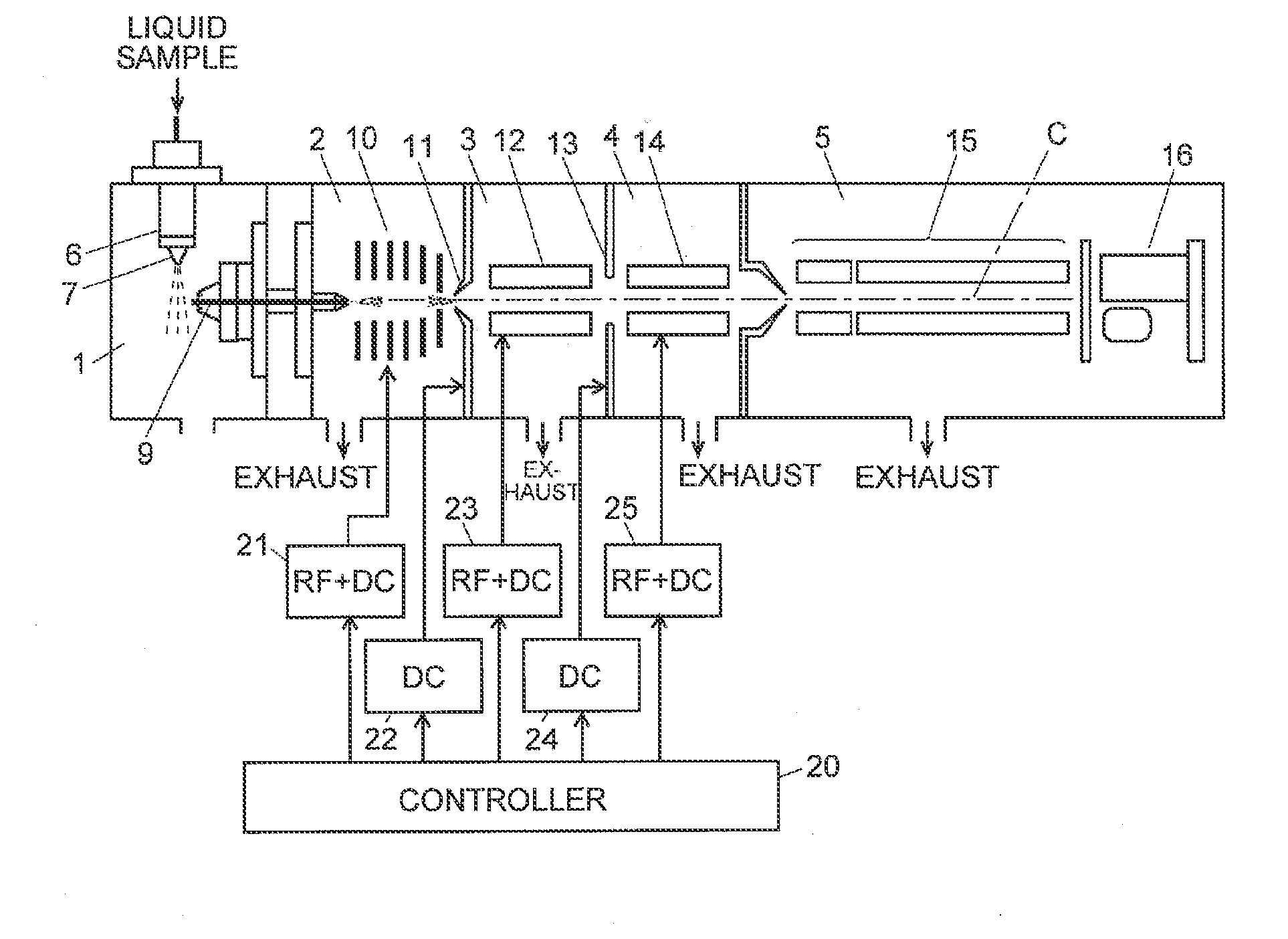
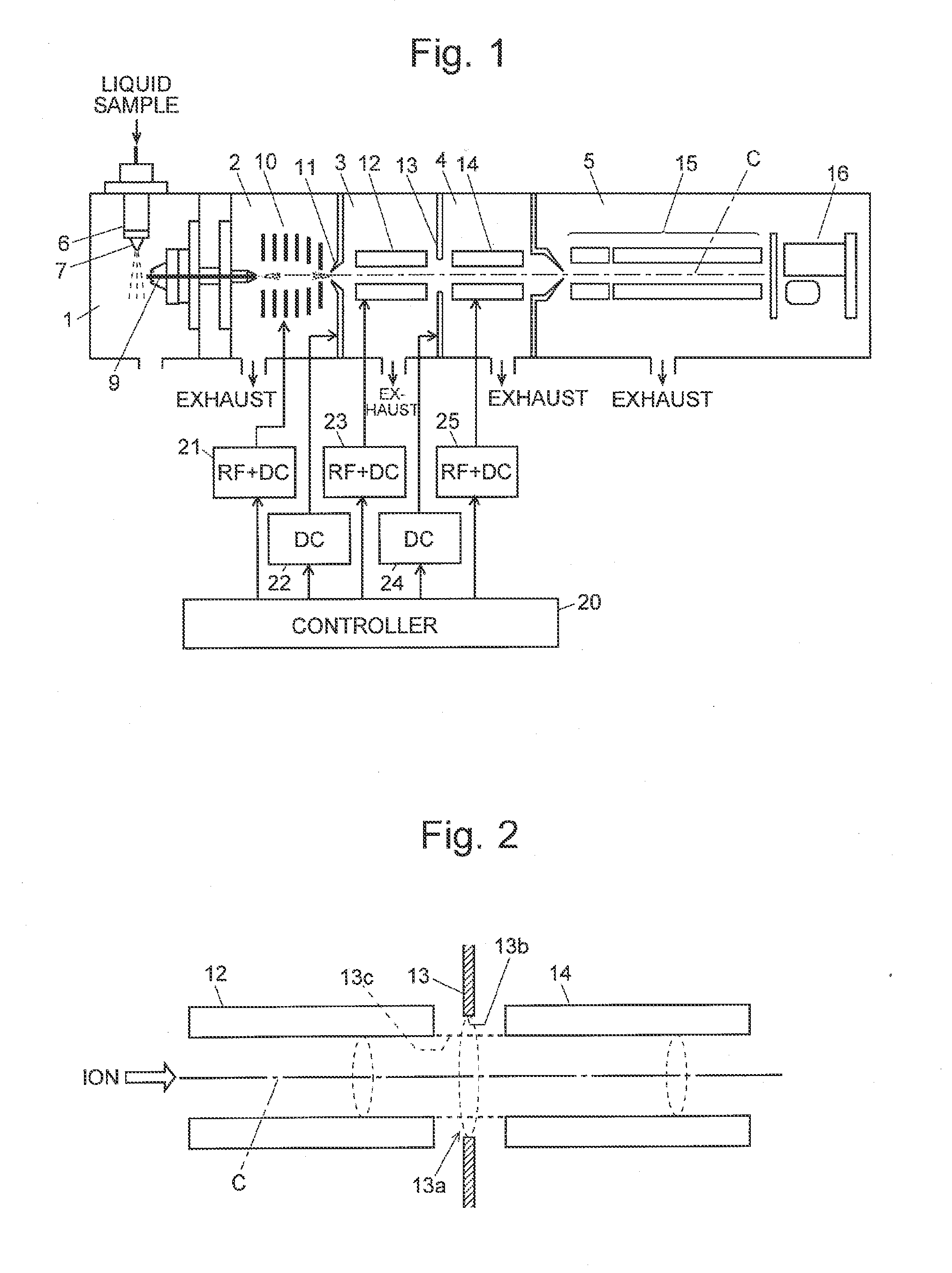
[0037]FIG. 1 is a schematic configuration diagram of a mass spectrometer according to the first embodiment, and FIG. 2 is a schematic configuration diagram of an ion transport optical system including ion guides and an ion lens characteristic of the mass spectrometer of the first embodiment.

[0038]The atmospheric pressure ionization mass spectrometer of the present embodiment includes an ionization chamber 1 maintained at approximately atmospheric pressure, an analyzing chamber 5 maintained in a high vacuum state by evacuation using a turbo-molecular pump or similar vacuum pump (not shown), as well as a first intermediate vacuum chamber 2, a second intermediate vacuum chamber 3 and a third intermediate vacuum chamber 4 each of which is maintained at an intermediate gas pressure between the gas pressure in the ionization chamber 1 and the gas pressure in the analyzing chamber 5 by evacuation using a vacuum pump. That is to say, the present atmospheric pressure ionization mass spectrom...


PUM


Abstract

A mass spectrometer having a multi-stage differential pumping system with an ion lens provided in a partition wall separating a second intermediate vacuum chamber and a third intermediate vacuum chamber, the incircle radii of ion guides and the size of the opening of the ion lens are determined so that the circumferential edge of the opening is located outside the circumferential surface of a virtual tubular body straightly connecting the incircle at the rear edge of the second ion guide in the front stage and the incircle at the front edge of the third ion guide in the rear stage. Although the ion lens is located in between, the radio-frequency electric field created by the second ion guide can be effectively connected to the radio-frequency electric field created by the third ion guide through the opening of the ion lens.

Description

TECHNICAL FIELD[0001]The present invention relates to a mass spectrometer, and more specifically, to an ion transport optical system for transporting ions to the subsequent stage in a mass spectrometer.BACKGROUND ART[0002]In a mass spectrometer, an ion optical element called an “ion guide” is used in order to focus ions coming from the previous stage and send them into a mass analyzer, such as a quadrupole mass filter. A typical structure of the ion guide is a multi-pole structure having four, six or eight columnar (or tubular) rod electrodes aligned parallel to each other around an ion-beam axis. Normally, in these types of multi-pole ion guides, two radio-frequency voltages having the same amplitude with opposite phases are applied to the rod electrodes in such a manner that one radio-frequency voltage is applied to a pair of rod electrodes facing each other across the ion-beam axis while the other radio-frequency voltage is applied to another pair of rod electrodes which are adja...

Claims


Application Information

Patent Timeline
Patent Type & Authority Applications(United States)
IPC IPC(8): H01J49/24H01J49/06
CPCH01J49/063H01J49/24H01J49/067
Inventor OKUMURA, DAISUKEUEDA, MANABU
Owner SHIMADZU CORP
Why Eureka
Try Eureka