Light coupling structures for optical touch panels

a technology of optical touch panel and light coupling structure, which is applied in the direction of instrumentation, lighting and heating apparatus, planar/plate-like light guide, etc., can solve the problems of difficult and/or costly optical access to edge surfaces, unsatisfactory attachment of light sources, and difficulty in optical accessing edge surfaces. to achieve uniform touch sensitivity

Inactive Publication Date: 2014-09-11
FLATFROG LAB
View PDF1 Cites 43 Cited by
  • Summary
  • Abstract
  • Description
  • Claims
  • Application Information

AI Technical Summary

Benefits of technology

[0033]In one embodiment, the panel has a first index of refraction and the optical component has a second index of refraction that exceeds the first index of refraction. Since light is refracted away from the normal at transition from a higher to a lower index of refraction, such a difference in index of refraction will cause the second component divergence to be refracted towards larger angles of incidence inside the panel. Thereby, the difference in index of refraction may allow a larger second component divergence angle to fit within a given range of angles of incidence inside the panel.
[0034]The first component divergence angle may be seen to represent a divergence in an azimuth angle with respect to the second light transmissive surface, and the second component divergence angle may be seen to represent a divergence in an elevation angle with respect to the second light transmissive surface. With this definition, one embodiment of the optical component may be designed to provide essentially the same second component divergence angle for all azimuth angles within the first component divergence angle. This will allow the touching object(s) to be illuminated in approximately the same way (same confined range of angles of incidence inside the panel with respect to the boundary surfaces) at all locations on the touch surface and thereby ensure a consistent interaction (touch sensitivity) between the light and touching object(s) across the touch surface. It will also enable a uniform touch sensitivity within the field of view inside the panel when the optical component is used for outcoupling.

Problems solved by technology

It may be undesirable to attach the light source to the edge surface, since this may impose mechanical load on soldering seams between the light source and a connecting substrate such as a PCB (Printed Circuit Board).
Defect free edge surfaces may be difficult and / or costly to achieve, especially if the panel is thin and / or manufactured of a comparatively brittle material such as glass.
It may also be difficult to optically access the edge surface if the panel is attached to a mounting structure, such as a frame or bracket, and the mounting structure may cause strain in the edge surface, affecting the optical quality of the edge surface and resulting in reduced incoupling performance.
The revolved prism is a bulky component which may add significant weight and size to the touch system.
Even a small or local detachment of the prism may cause a significant decrease in the performance of the system.
The light may be detected by light detectors directly attached to the edge surface, but this may cause the light detectors to also act as mirrors to the light in the panel at certain angles of incidence, potentially causing uncontrolled and undesirable reflections inside the panel.
In either case, this may lead to mechanical load on soldering seams between the detector and a connecting PCB.
Furthermore, reducing the extent of the second light transmissive surface, i.e. the surface used for attaching the component to the panel, may result in lower stress in the bond between the component and the panel due to differences in thermal expansion.
However, the use of an air gap results in a step change in index of refraction at the first light transmission surface, which may cause the emitted cone of light to be compressed when it enters the component through the first light transmissive surface.
Such reflected light, which may originate from ambient light or from light coupled into the panel, may result in an uncontrolled and undesirable light distribution inside the panel.

Method used


Image

  • Light coupling structures for optical touch panels
  • Light coupling structures for optical touch panels
  • Light coupling structures for optical touch panels

Examples


first embodiment

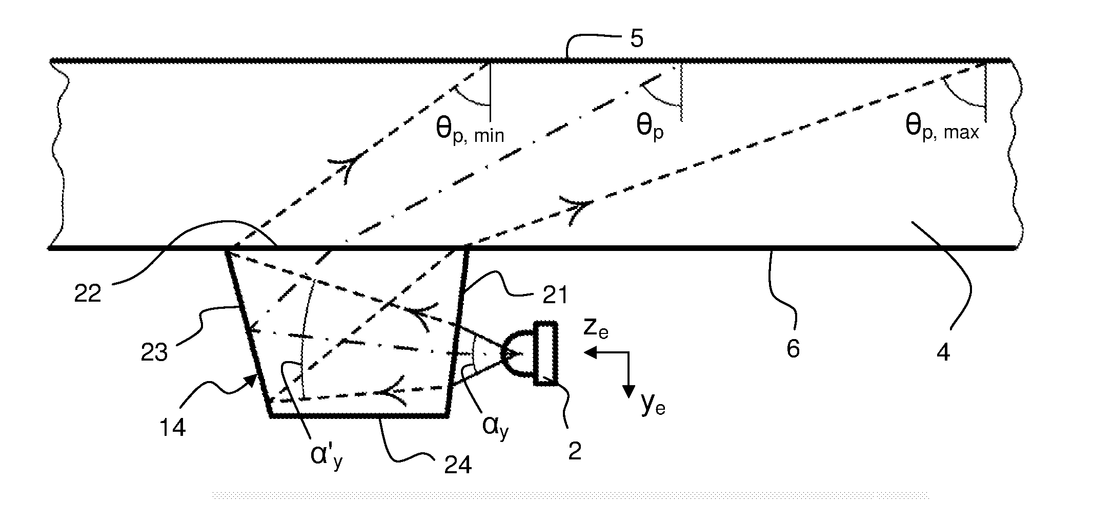
[0096]FIG. 6 is a perspective view of the incoupling element 14 as attached to the bottom boundary surface 6 of the panel 4, e.g. by means of an optical adhesive. The incoupling element 14 is made of an optically transparent material and comprises a planar light entry face 21 arranged to project from the panel 4, a planar light exit face or attachment surface 22 arranged to face and be affixed to the boundary surface 6, and a three-dimensional control surface 23 which is designed with respect to the solid angle Ω (FIG. 3) of the emitter 2 so as to achieve the desired panel divergence φp, main direction zp and bounce angle θp of the injected light. A coordinate system is defined at the center of the exit face, with zc extending normal to the exit face, and xc extending parallel to the main direction (zp) of the light coupled into the panel 4.

[0097]FIG. 7 is a top plan view of the first embodiment as attached to the panel 4 and combined with an emitter 2. FIG. 7 illustrate defining li...

second embodiment

[0114]FIGS. 14A-14B are elevated side views, taken from mutually orthogonal sides, of an incoupling element 14 according to a The incoupling element 14, which is attached to the bottom boundary surface 6 of the panel 4, is designed as an elongate light guide of light transmissive material that defines an entry face 21 at one end and an exit face 22 at the other end. The light guide 14 comprises a first pair of elongate opposing control surfaces 30, 31 that expand the emitter divergence αx into a component divergence φc at the exit face 22, resulting in a desired panel divergence φp inside the panel 4. As shown in FIG. 14A, the control surfaces 30, 31 taper from the entry face 21 to the exit face 22, as seen in a first geometric plane which extends along the light guide 14 and coincides with the xe-ze-plane of the emitter. Thereby, the reflection angle of the light propagating between the control surfaces 30, 31 is decreased for every reflection inside the light guide 14, whereby th...


PUM

PropertyMeasurementUnit
widthaaaaaaaaaa
widthaaaaaaaaaa
solid angleaaaaaaaaaa

Abstract

A coupling element (14) for use in a touch-sensitive apparatus is arranged to transfer light between an electro-optical device (2) and a panel (4) for light transmission. The electro-optical device (2) is an emitter or a detector and has an operative solid angle given by orthogonal device divergence angles. The coupling element (14) is an optical component with a first light transmission surface (21) for facing the electro-optical device (2), and a second light transmission surface (22) for mounting on the panel (4). The coupling element (14) has an optical structure (23) that directs the light between the first and second light transmission surfaces (21, 22) by one or more reflections while expanding one device divergence angle (αx) into a component divergence angle at the second light transmission surface (22). Thereby, the component divergence angle defines a divergence (φp) in the plane of the panel (4) with respect to light propagating by internal reflections inside the light transmissive panel (4).

Description

CROSS-REFERENCE TO RELATED APPLICATIONS[0001]The present application claims the benefit of Swedish patent application No. 1150810-8, filed 9 Sep. 2011, and U.S. provisional application No. 61 / 532,655, filed 9 Sep. 2011, both of which are incorporated herein by reference.TECHNICAL FIELD[0002]The present invention relates to touch-sensitive systems that operate by light transmission inside light transmissive panels, and in particular to optical solutions for coupling light into and out of such panels.BACKGROUND ART[0003]The prior art comprises different types of touch-sensitive systems that operate by transmitting light inside a solid light transmissive panel, which defines two parallel boundary surfaces connected by a peripheral edge surface. Specifically, light is injected into the panel so as to propagate by total internal reflection (TIR) between the boundary surfaces. An object that touches one of the boundary surfaces (“the touch surface”) causes a change in the propagating ligh...

Claims


Application Information

Patent Timeline
Patent Type & Authority Applications(United States)
IPC IPC(8): G06F3/042F21V8/00
CPCG02B6/002G06F3/0428G06F3/0421G06F2203/04109G02B6/0018G02B6/0028
Inventor CRAVEN-BARTLE, THOMAS
Owner FLATFROG LAB
Why Eureka
Try Eureka