

Forming Composite Features Using Steered Discontinuous Fiber Pre-Preg
a discontinuous fiber and composite technology, applied in the direction of process and machine control, instruments, mechanical control devices, etc., can solve the problems of inability to control local thickness/fiber orientation, inability to achieve close control of thickness and/or fiber orientation in local areas with tight contours, and inability to achieve local thickness/fiber orientation. control, the effect of optimizing the structural properties of the lamina
- Summary
- Abstract
- Description
- Claims
- Application Information
AI Technical Summary
Benefits of technology
Problems solved by technology
Method used
Image

Examples
Embodiment Construction
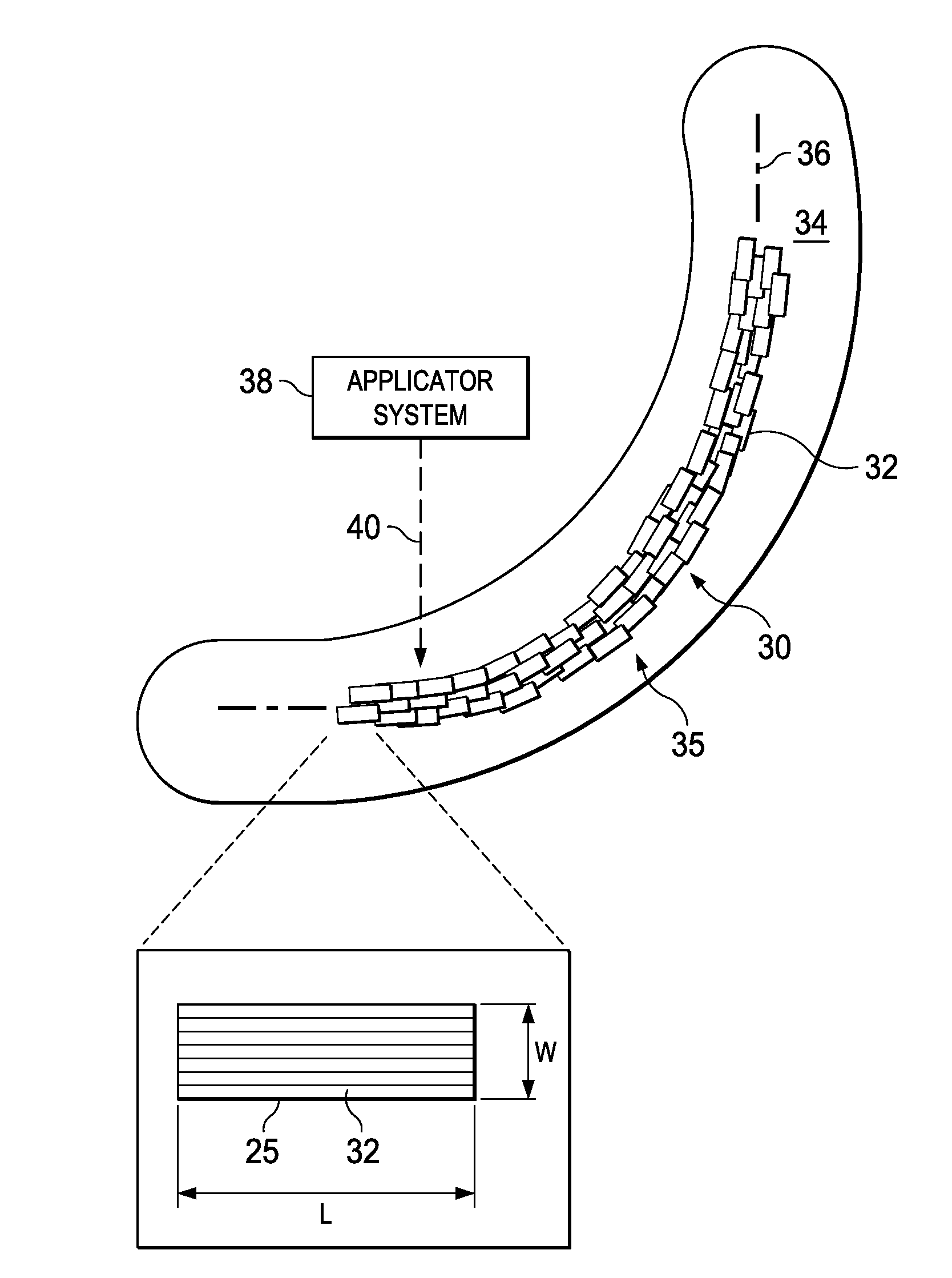
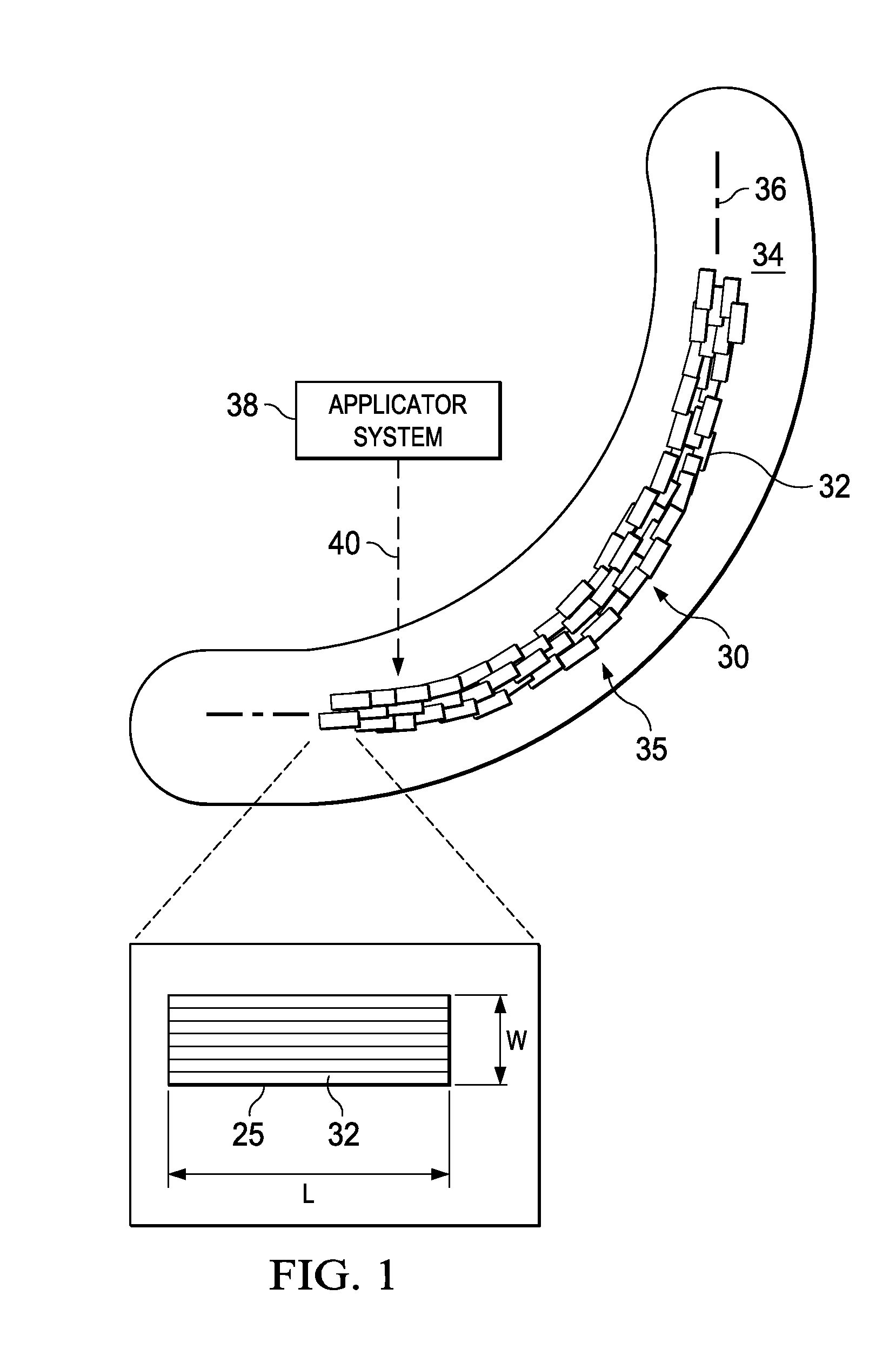
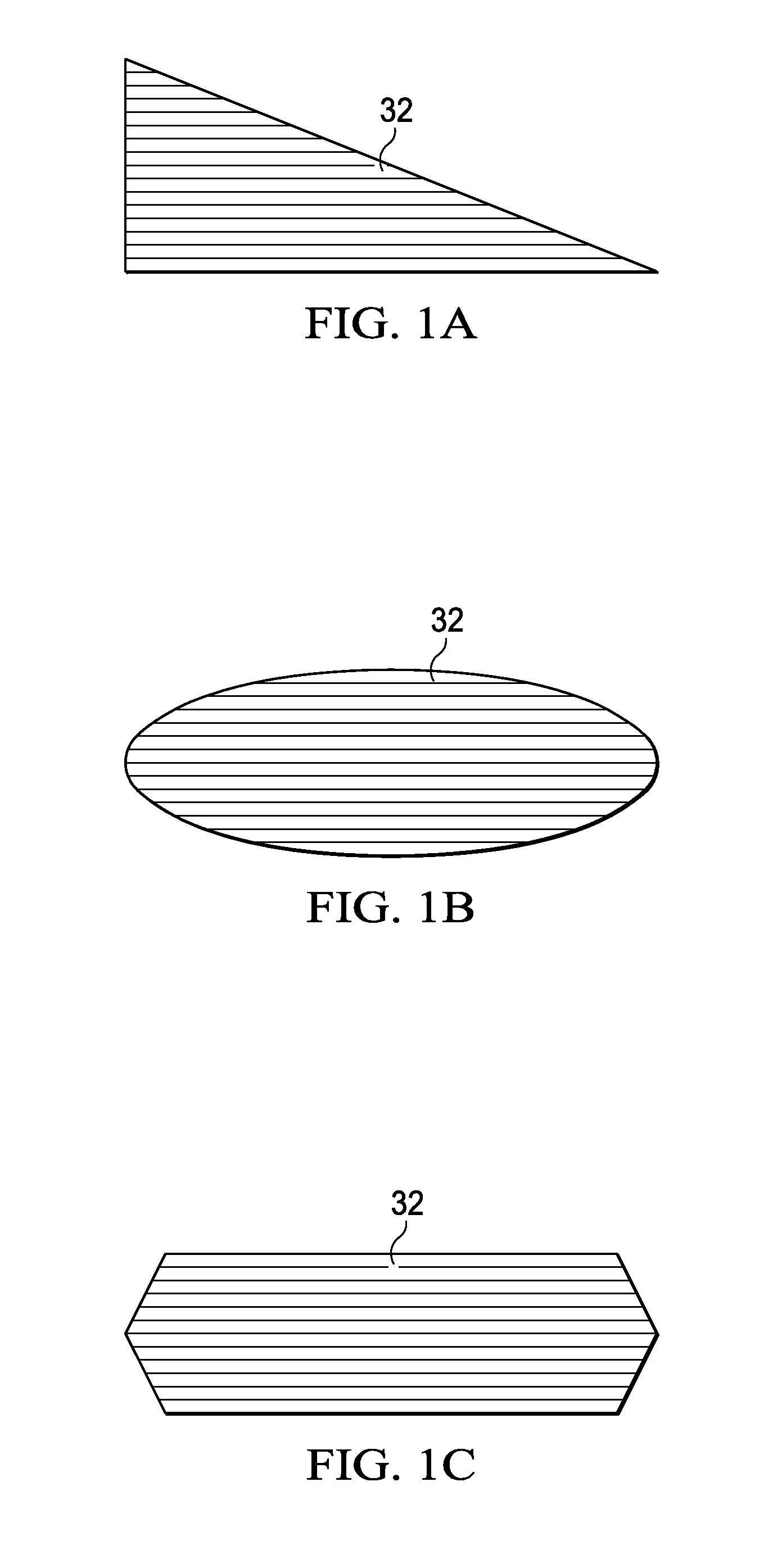
[0050]The disclosed embodiments provide a method and apparatus for fabricating fiber reinforced resin laminates which provide increased control over laminate thickness, contour, width, cross-sectional profile and / or fiber orientation in local areas of a laminate structure. Referring to FIG. 1, a composite feature 30 comprises discontinuous, resin infused fibers which may be in the form of chopped fiber pre-preg segments 32 having unidirectional reinforcing fibers 25. Each of the fiber pre-preg segments 32 is elongate, having a length L that is greater than its width W. Each of the fiber pre-preg segments 32 may have an aspect ratio (L / W) in the range of approximately 6:1, however this particular ratio is merely illustrative. The fiber pre-preg segments 32 may have other aspect ratios that are selected and / or optimized for the application, including structural requirements and the equipment used to position or place the segments 32. In some embodiments, the fiber pre-preg segments 32...
PUM
| Property | Measurement | Unit |
|---|---|---|
| Length | aaaaa | aaaaa |
| Aspect ratio | aaaaa | aaaaa |
Abstract
Description
Claims
Application Information