
Method for producing a metal part for an aircraft turbo-engine

a metal part and turbo-engine technology, applied in the direction of turbines, manufacturing tools, mechanical equipment, etc., can solve the problems of high cost of moulding, defect that can directly affect the mechanical strength of the part, and the production method remains slow, so as to achieve the effect of low cost and slow production of the par

Active Publication Date: 2014-09-18
SN DETUDE & DE CONSTR DE MOTEURS DAVIATION S N E C M A
View PDF0 Cites 10 Cited by
  • Summary
  • Abstract
  • Description
  • Claims
  • Application Information

AI Technical Summary

Benefits of technology

The invention proposes a solution to problems associated with selective melting by laser or electron beam, such as slow production and potential mechanical defects. The method is cost-effective and suitable for parts with frequently changing geometry.

Problems solved by technology

However, for metal parts having portions of relatively large thickness, such a production method remains slow: in fact, each of the different successive layers has a thickness comprised between twenty and one hundred micrometres, and the number of passages of the energy source of laser beam or electron beam type is thus high.
Said particles or ejections then fall back onto the surface that has to undergo the following passage of the beam, which can be the source of production defects, defects capable of directly impacting the mechanical strength of the part.
A first solution resides in the production of metal parts by machining from a block of material; but within the framework of the development of these parts, during which their geometry is capable of being frequently modified, such a solution is not suitable; it would then in fact be necessary to adapt, for each of the considered parts, in particular the machining cycle and the tools for positioning the part.
Such a solution may prove to be interesting uniquely for parts produced in large numbers, because the mould to use is very costly.
Such a solution is absolutely not viable within the context of the development of a turbo-engine during which the geometry of the considered parts may constantly evolve.

Method used


Image

  • Method for producing a metal part for an aircraft turbo-engine
  • Method for producing a metal part for an aircraft turbo-engine

Examples


Embodiment Construction

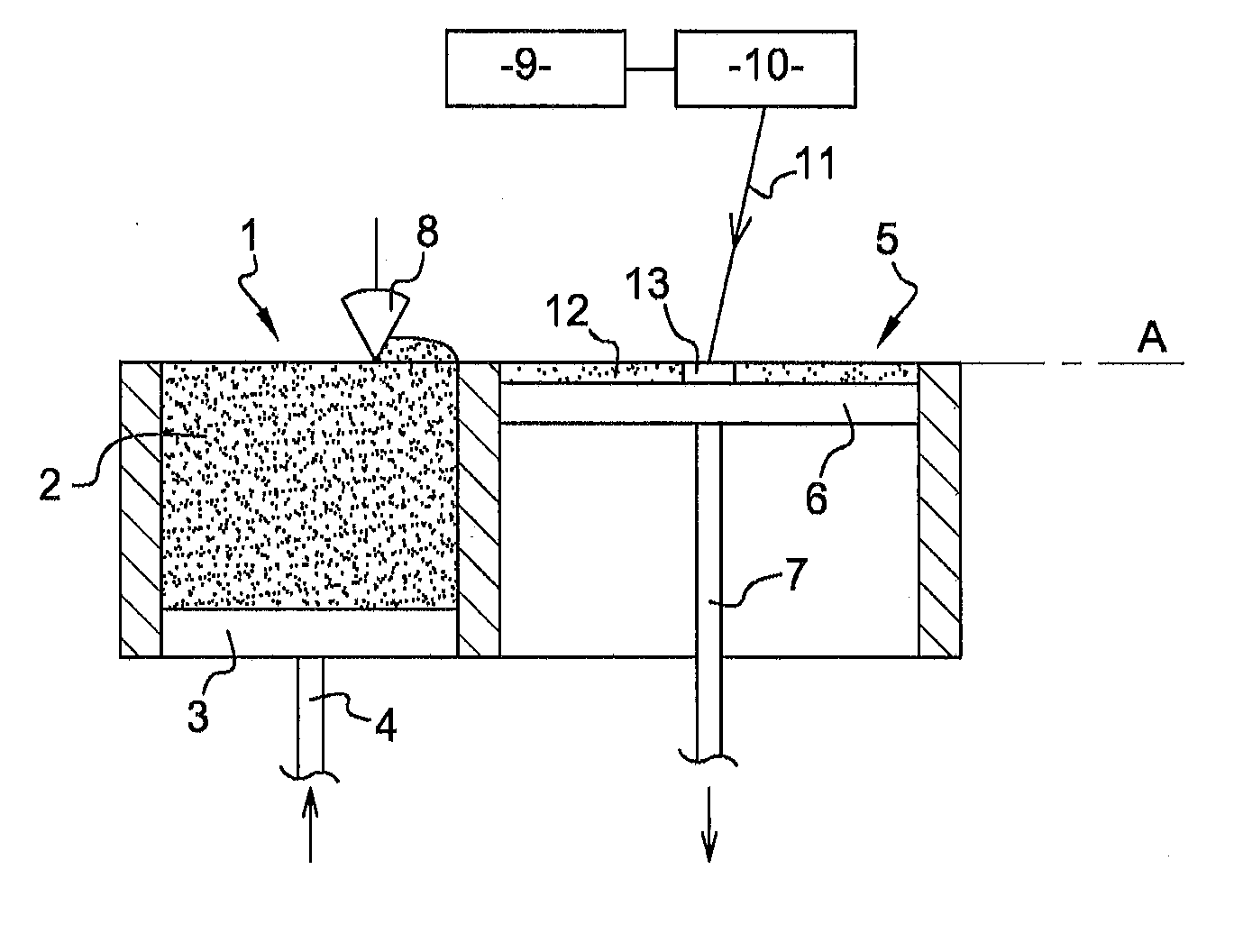
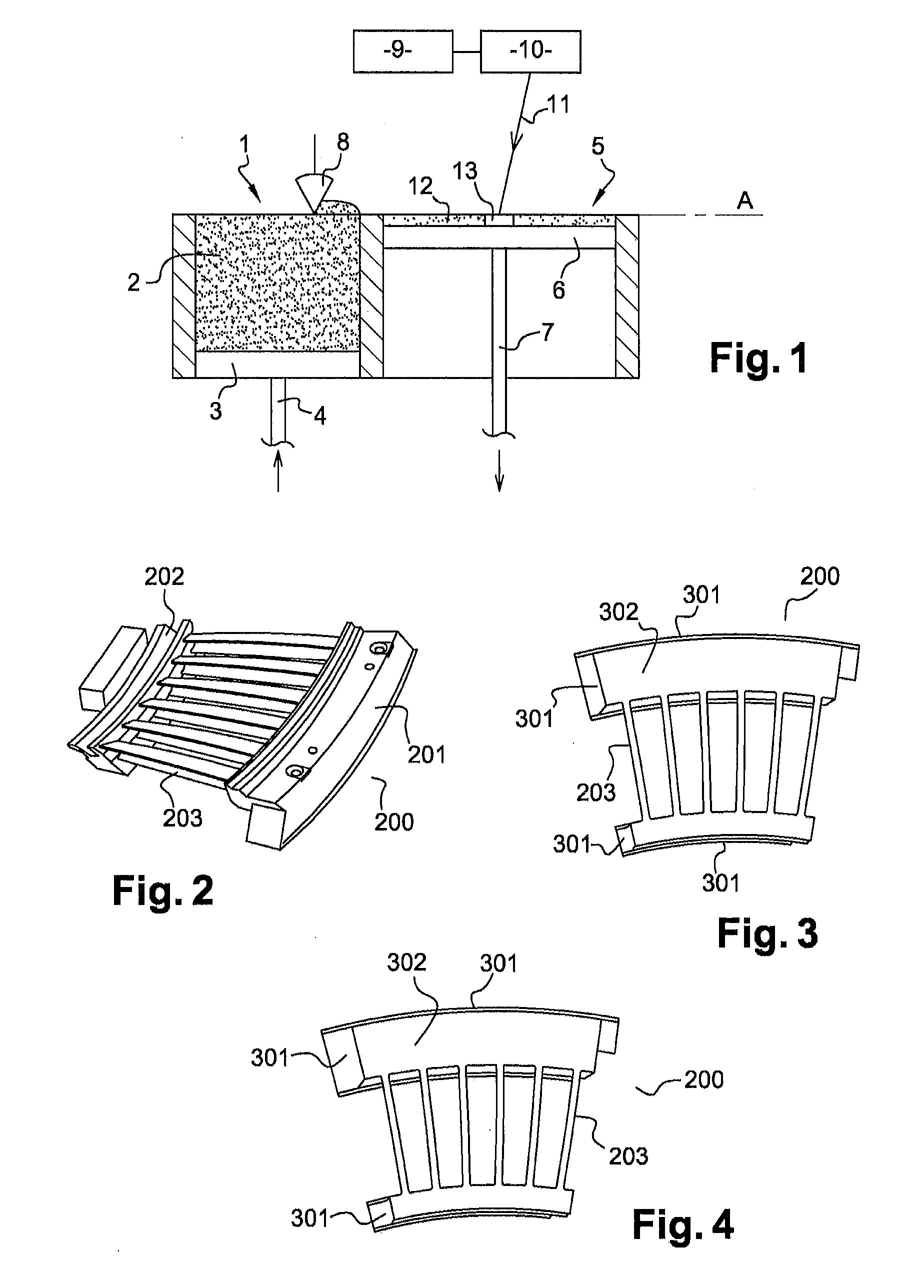
[0032]An installation for producing a metal part by selectively melting a powder is represented in FIG. 1. Such an installation is advantageously used for the implementation of the method according to the invention, for the production of elements of small thickness present in the considered part.

[0033]The installation represented comprises a reservoir 1 containing a metal powder 2 and the bottom 3 of which is mobile and moveable in translation by a rod 4 of a jack, and a neighbouring vessel 5, the bottom of which is constituted of a moveable plate 6, also translationally moveable by a rod 7 of a jack. The installation further comprises a scraper 8 making it possible to bring the powder of the reservoir 1 to the vessel 5, by movement along a horizontal plane A, and means 9 of generating a laser beam or an electron beam, coupled to a device 10 making it possible to direct and to move the beam 11.

[0034]The steps of producing a metal part by means of this installation are the following....


PUM

PropertyMeasurementUnit
Thicknessaaaaaaaaaa
Thicknessaaaaaaaaaa
Lengthaaaaaaaaaa

Abstract

A method for producing a metal part, the part including, in particular, a first set of elements having a small thickness, and a second set of elements having a large thickness, the method including: forming a peripheral portion of the elements of the second set of elements by selectively melting a powder by scanning the surface of the powder layer with a laser beam or with an electron beam; using the peripheral portion of the elements of the second set of elements as a mould by carrying out an operation of filling an inner area defined by the peripheral portion with liquid metal; cooling the metal part to solidify the inner area defined by the peripheral portion and filled with metal.

Description

TECHNICAL FIELD OF THE INVENTION[0001]The present invention relates to a method for producing a metal part used in an aircraft turbo-engine. Without being limiting, the metal part considered is advantageously for example a turbo-engine high pressure turbine, or a low pressure turbine; but the method according to the invention can apply to any metal part having thin portions, with a thickness not exceeding several millimetres, associated with thicker portions, having a thickness of several centimetres.[0002]The technical field of the invention is thus, generally speaking, that of aircraft engines and, more particularly, that of the production of metal parts forming said engines.TECHNOLOGICAL BACKGROUND OF THE INVENTION[0003]A particular method is today favoured for producing certain metal parts for aircraft turbo-engines; it resides in a method of selectively melting a powder using a directed beam, of laser beam or electron beam type. Such a method is known under the names of Direct ...

Claims


Application Information

Patent Timeline
IPC IPC(8): B22D23/06B22D25/02B23P15/02
CPCB22D23/06B22D25/02B23P15/02B22D19/00B22F5/009B22F5/04B22F7/08B22D19/04C22C19/056Y02P10/25B22F10/28B33Y10/00B23K26/144B23K26/342B22F3/105C23C24/10
Inventor VILARO, THOMASRIX, SEBASTIENBAUDIMONT, CYRILLE
Owner SN DETUDE & DE CONSTR DE MOTEURS DAVIATION S N E C M A
Learn More