Fin Spacing On An Evaporative Atmospheric Water Condenser

a technology of evaporative atmospheric water condensers and fin spacing, which is applied in the direction of ice removal, heat exhanger fins, lighting and heating apparatus, etc. it can solve the problems of insufficient heat transfer, affecting the effectiveness of coils, and water layers closest to the coils may freez

Inactive Publication Date: 2014-09-18
AVYA GREEN TECH PVT LTD
View PDF12 Cites 18 Cited by
  • Summary
  • Abstract
  • Description
  • Claims
  • Application Information

AI Technical Summary

Benefits of technology

[0004]Currently, evaporators are fabricated with a specified fins per inch characteristic such as 6 fins per inch, 8 fins per inch or 12 fins per inch etc. The current invention is directed to fin spacing where a certain section of the evaporator has (for example) 6 fins per inch and another section 12 fins per inch. In order to have different fin spacing in different portions of the evaporator, spacers are introduced on the evaporator coils that allows changing fin spacing (fins per inch or fins per centimeter). This has the effect of altering the overall heat transfer coefficient of the system. Additionally, it permits a continuous air flow between the fins.
[0009]Properly spaced fins that are optimized for each section of the evaporator are easy to analyze and thus optimize through simulations of computational fluid models. In the approach presented here, the use of fin spacers can also be applied to any fin design.
[0010]To provide the ideal flow regimes and fin surface temperatures at different sections of an evaporator coil, a novel method of fin fabrication is utilized. Although evaporator fins on coils are currently fabricated utilizing different techniques, they share a common modality which would ensure that the fins are tightly attached to the coils so that contact resistance is minimized.
[0012]The invention comprises spacers of different widths which are placed over the coil columns. Different width spacers may be used on different columns in the apparatus. The amount of space between a fin on a single coil column caused by the spacers being intermediate two fins would modulate the heat transfer characteristics in different sections of the coil. To create the variation in spacing between fins, spacers can also be introduced between fin sheets that can vary from section to section of the apparatus. Additionally, different width spacers may be placed on different coil columns. The coil columns are parallel to each other as are the fins. Many fin variations are possible. For instance, in the same apparatus, some fins may still be spaced by the dimple, while others fins may be spaced by a spacer of a first width, and still other fins be spaced by a spacer having a third width. The use of spacers permits fins to be staggered and inter-spaced in the space between the parallel coil columns. Spacers may be used between some of the fins on a first coil while different sized spacers may be used on fins on a second coil, or even a third coil. A large number of fin configurations therefore may be employed, allowing a great variation in the number of different atmospheric water condenser devices.

Problems solved by technology

Fins are used to extend the surface available for heat transfer, and their aspect ratio, material, and attachment to coils affects their effectiveness.
This can be caused by insufficient heat transfer, or insufficient heat transfer prior to air passing over a specific fin, or if the temperature of the fin surface is higher than the dew point temperature of the moist air.
If the water film gets too thick and does not allow enough heat flow, the water layers nearest to the coils may freeze.

Method used


Image

  • Fin Spacing On An Evaporative Atmospheric Water Condenser
  • Fin Spacing On An Evaporative Atmospheric Water Condenser
  • Fin Spacing On An Evaporative Atmospheric Water Condenser

Examples


first embodiment

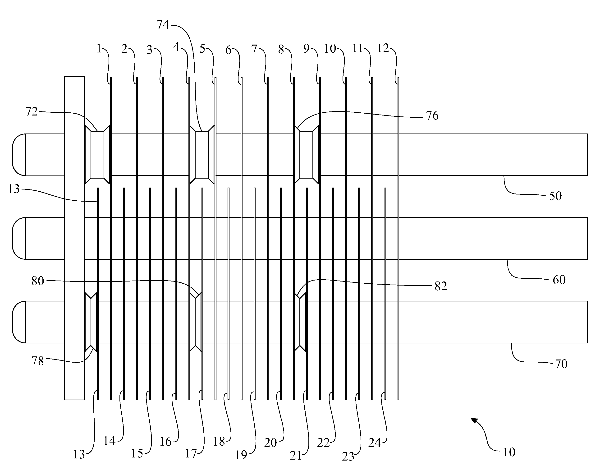
[0019]Referring to FIG. 1, a view of a three column coil evaporator for a water generating apparatus 10 is shown. There are three serpentine refrigerant coils in which the refrigerant enters on the right and flows downward to three refrigerant exits (best seen in FIG. 3). The rear refrigerant coil 50, the center refrigerant coil 60 and the front refrigerant coil 70 are shown from the bottom of FIG. 1. Initially, as the refrigerant enters the rear refrigerant coil 50, the center refrigerant coil 60 and the front refrigerant coil 70, it is in its coldest condition. Finally, as the refrigerant exits the rear refrigerant coil 50, the center refrigerant coil 60 and the front refrigerant coil 70, it is in its warmest condition. Conventional methods are employed to cool the refrigerant in these closed loop refrigerant coils.

[0020]Surrounding the rear refrigerant coil 50, the center refrigerant coil 60 and the front refrigerant coil 70 is a plurality of fins, individually numbered fin eleme...

second embodiment

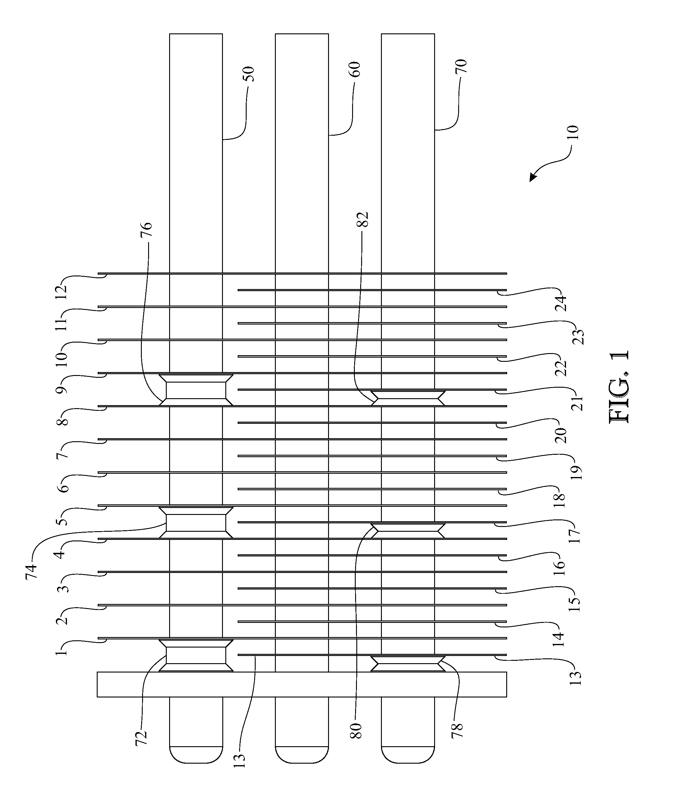
[0037]Referring to FIG. 2, a view of a three column coil evaporator for a water generating apparatus 10′ is shown. In this embodiment the top refrigerant coil 50′, the center refrigerant coil 60′ and the bottom refrigerant coil 70′ are shown. In this embodiment the top refrigerant coil 50′ has twelve spacers 80′ placed along its length. Additionally, the bottom refrigerant coil 70′ has twenty-four spacers 82′ placed along its length.

[0038]Except for the leftmost spacer 80′ on rear refrigerant coil 50′ each pair of spacers 80′ has a fin of the configuration of group 1 intermediately located. At the intersection of each spacer 80′ a fin element is located. Referring to the top refrigerant coil 50′, fins 1′-12′ are intermediate each of the spacers 80′ and each fin selected from the fins of the configuration of group 1. The three refrigerant coils (50′, 60′, 70′) have fins 1′-12′ mounted thereon, each spaced the width of one of the spacers 80′.

[0039]Similarly to the embodiment shown in ...

third embodiment

[0044]Referring now to FIG. 4, a view of a three column coil evaporator of a water generating apparatus 200 is shown. A first set of wider spacers 215 are placed on the rear refrigerant coil 210. A second set of smaller width spacers 222 are placed on the center refrigerant coil 220. A third set of the same smaller width spacers 232 are placed on the front refrigerant coil 230. The second set of smaller width spacers 222 are essentially the same width as the third set of smaller width spacers 232.

[0045]The rear refrigerant coil 210 shows twelve spacers 215. The spacers 215 are of equal width. These spacers 215 are not limited to twelve and would extend the length of the horizontal portion of the rear refrigerant coil 215.

[0046]The center refrigerant coil 220 shows twenty-four smaller spacers 222. The smaller spacers 222 are of equal width. These smaller spacers 222 are about ½ the width of the larger spacers 215.

[0047]The front refrigerant coil 230 includes twenty-four smaller space...


PUM


Abstract

An improvement in atmospheric evaporative water condenser is disclosed. The apparatus includes tubes through which a refrigerant would pass and a variety of generally rectangular or circular fins are in contact with the tubes which causes the fins to cool. This permits water in its vapor form which exists in atmospheric air to condense on the fins and the condensate is collected as potable water. The improvement includes a plurality of different width spacers which are toleranced to be placed over the tubes and secured in desired positions. The fins are placed between the spacers allowing different fin spacing configurations on the apparatus. The different fin configurations optimize airflow for different coil and fin sections and help prevent water flooding or frost buildup on the fins which impair efficiency. Also, the spacers allow the fins to be placed far enough apart that non-frozen condensate does not block the air flow through the space between the fins.

Description

RELATED PATENT APPLICATIONS [0001]This utility patent application claims priority from Provisional Patent Application Ser. No. 61 / 788,718 filed on Mar. 15, 2013 titled “Fin Spacing on an Evaporative Atmospheric Water Condenser”, Provisional Patent Application Ser. No. 61 / 789,372 filed on Mar. 15, 2013, titled “Refrigerant Flow Control For an Evaporative Atmospheric Water Condenser”, and Provisional Patent Application Ser. No. 61 / 831,231 filed on Jun. 5, 2013 titled “Refrigerant Flow Control For an Evaporative Atmospheric Water Condenser” all of which are incorporated herein in their entirety.BACKGROUND OF THE INVENTION[0002]Devices which extract water from the atmosphere employ a refrigerant which is pumped through a tortuous pipe with a plurality of fins affixed to the pipe. These fins will cool by action of the refrigerant and water would condense on the fin surface and be collected for use. The efficiency of such devices which remove water from the air is impaired when the water ...

Claims


Application Information

Patent Timeline
Patent Type & Authority Applications(United States)
IPC IPC(8): F28F1/12
CPCF28F1/12F28D1/0477F28D2021/0038F28F1/32F28F17/005F28F2215/04F28F2240/00
Inventor SISTLA, RAMANA VENKATO RAO
Owner AVYA GREEN TECH PVT LTD
Why Eureka
Try Eureka