Centrally threaded plug for heat exchanger tube and removal tool

a technology of heat exchanger tubes and threaded plugs, applied in the field of tube plugs, can solve the problems of pin holes, cracks, pin holes, etc., and achieve the effect of reducing or eliminating the damage to heat exchange tubes and tubesheets, minimizing repair expenditures and avoiding operation production losses

Active Publication Date: 2014-09-18
SAUDI ARABIAN OIL CO
View PDF9 Cites 5 Cited by
  • Summary
  • Abstract
  • Description
  • Claims
  • Application Information

AI Technical Summary

Benefits of technology

[0037]By implementing this improved plug, the concern of damage to heat exchange tubes and tubesheets will be greatly reduced or eliminated. Also, the cost of a new tubesheet as a replacement for the defective one, repair expenditures and operation prod...

Problems solved by technology

U.S. Pat. No. 6,688,336 to Trichard discloses the concept of rotating a tube plug; however, this reference requires external threads on the tube plug to engage and cut into the bore of the plugged tube which is a relatively soft plastic, this device thus being not applicable to hard steel heat exchange tubes.
In the operation of heat exchangers, problems may occur from pin holes, cracks, clogging or other fluid seal issues in heat exchange tubes.
Due to the original interference fit, corrosion, heat changes which may be extreme and other factors du...

Method used


Image

  • Centrally threaded plug for heat exchanger tube and removal tool
  • Centrally threaded plug for heat exchanger tube and removal tool
  • Centrally threaded plug for heat exchanger tube and removal tool

Examples


Embodiment Construction

[0048]To facilitate an understanding of the invention, the same reference numerals have been used, when appropriate, to designate the same or similar elements that are common to the figures. Unless stated otherwise the features shown and described in the figures are not drawn to scale, but are shown for illustrative purposes only.

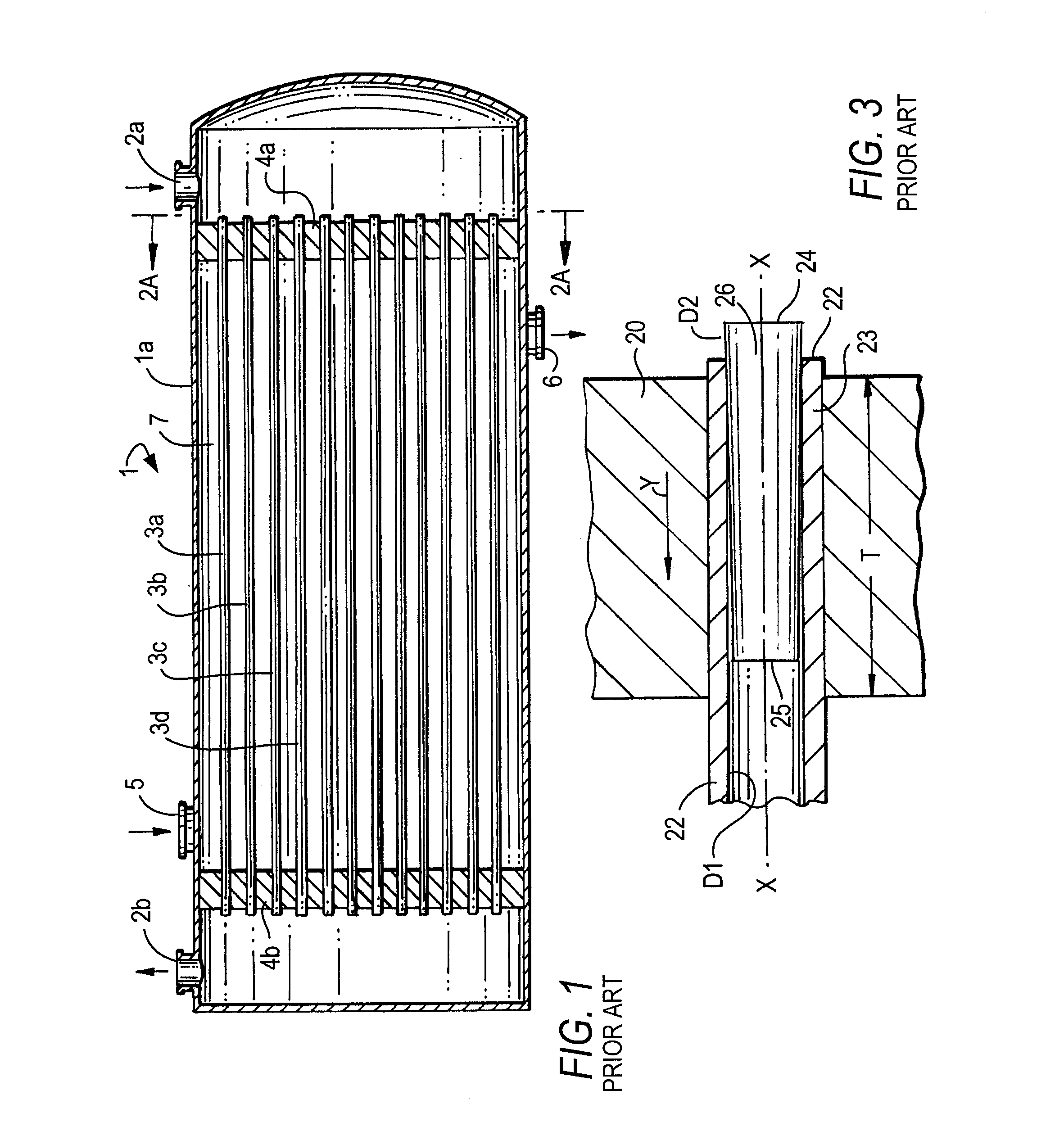
[0049]FIG. 1 shows a heat exchanger 1 including its shell is containing a plurality of generally parallel heat exchange tubes 3a, 3b, 3c, 3d extending axially between inlet 2a and outlet 2b. Each tube has its proximal end extending through and fixed to tubesheet 4a, and its distal end extending through and fixed to tubesheet 4b.

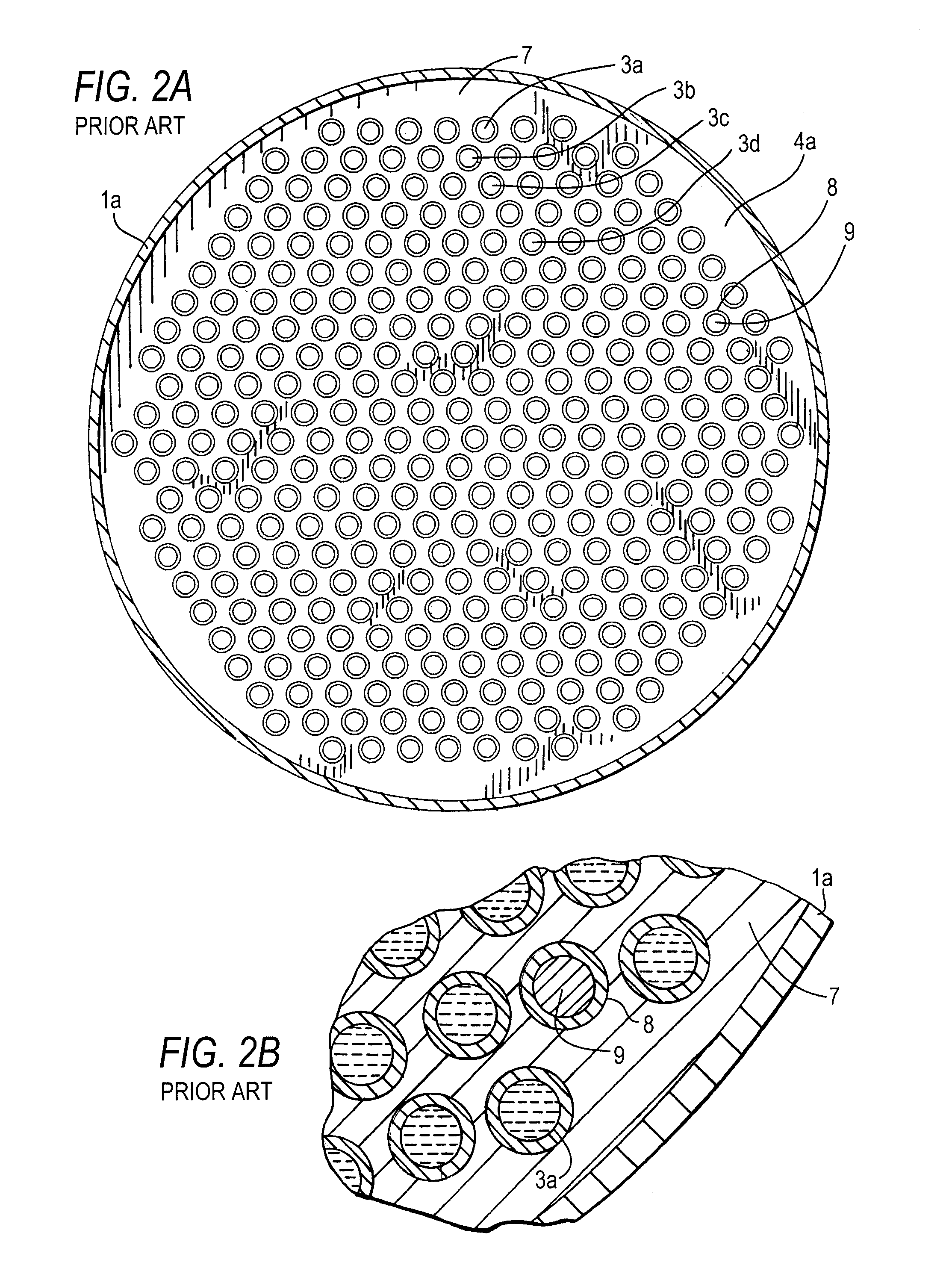
[0050]FIG. 2a shows the end face of the tubesheet 4a with its large number of transverse holes. In each hole the proximal end of one heat exchanger tube is tightly secured by conventional means, with four representative tubes 3a-3d so labeled. Tube 8 is shown with a tube plug 9 secured in its open end. FIG. 2b is an enlarged fragmen...


PUM

PropertyMeasurementUnit
Angleaaaaaaaaaa
Diameteraaaaaaaaaa
Lengthaaaaaaaaaa

Abstract

A tube plug insertable in one end of a heat exchange tube, the tube plug formed as an shaft having a distal part and an opposite proximal part which terminates in a proximal end with an threaded hole extending axially in the proximal end in the distal direction, and a plug removal tool having a proximal handle part and a distal stem part which has external threads that match threads in the threaded hole in the plug's shaft, the stem part being threadedly insertable into the threaded hole in the proximal end of the tube plug, whereby rotation of the stem will urge the tube plug to rotate relative to the heat exchange tube and break free from being lodged in the bore thereof.

Description

RELATED CASE[0001]This patent application claims benefit under 35 USC Sections 119 and / or 120 of U.S. Provisional Application No. 61 / 780,572 filed Mar. 13, 2013 the contents of which are incorporated herein by reference.I. BACKGROUND[0002]A. Field of the Invention[0003]This invention is in the field of tube plugs for heat exchange tubes used in heat exchangers, and particularly for tube plugs which tend to become tightly lodged in one end of a heat exchanger tube.[0004]B. Discussion of Prior Art[0005]This invention pertains to heat exchangers including shell and tube, air cooled, double pipe and other types. In conventional heat exchangers a plurality of heat exchange tubes are secured between opposing tubesheets with ends of the tubes tightly engaged in holes in the respective tubesheets. The ends of the heat exchange tubes are normally connected to the tubesheets using hydraulic expansion or hydraulic expansion and seal welding to achieve a fluid-tight seal intended to withstand e...

Claims


Application Information

Patent Timeline
IPC IPC(8): F28F99/00
CPCF28F99/00F28F11/02F16L55/13Y10T29/49822
Inventor AL-OTAIBI, DHAWI A.
Owner SAUDI ARABIAN OIL CO
Why Eureka
Try Eureka