Regenerative Power Supply System and Method

a power supply system and regenerative technology, applied in the direction of mechanical equipment, dc-ac conversion without reversal, greenhouse gas reduction, etc., can solve the problems of limiting reliable daily access to energy inputs, requiring energy inputs that once consumed cannot be reclaimed, and distributed (on-site) power generation methods involving solar energy also face the same limitation of being unable to regenerate their own energy inputs

Active Publication Date: 2014-09-18
CONSTRUCTIVE IND
View PDF5 Cites 29 Cited by
  • Summary
  • Abstract
  • Description
  • Claims
  • Application Information

AI Technical Summary

Problems solved by technology

They require energy inputs that once consumed cannot be reclaimed for use in a regenerative cycle of electricity production.
Other distributed (on-site) power generation methods involving harvesting renewable resources such as solar energy also face the same limitation of being unable to regenerate their own energy inputs.
Furthermore, renewable energy systems, when utilized alone are dependent on natural cycles such as seasonal fluctuations in potential energy available for harvesting and diurnal cycles that limit reliable daily access to energy inputs (e.g., sunlight).

Method used


Image

  • Regenerative Power Supply System and Method
  • Regenerative Power Supply System and Method
  • Regenerative Power Supply System and Method

Examples


Embodiment Construction

[0020]In the following detailed description of the preferred embodiment, reference is made to the accompanying drawings that form a part hereof, and in which is shown by way of illustration, and not by way of limitation, a specific preferred embodiment in which the invention may be practiced. It is to be understood that other embodiments may be utilized and that changes may be made without departing from the spirit and scope of the present invention.

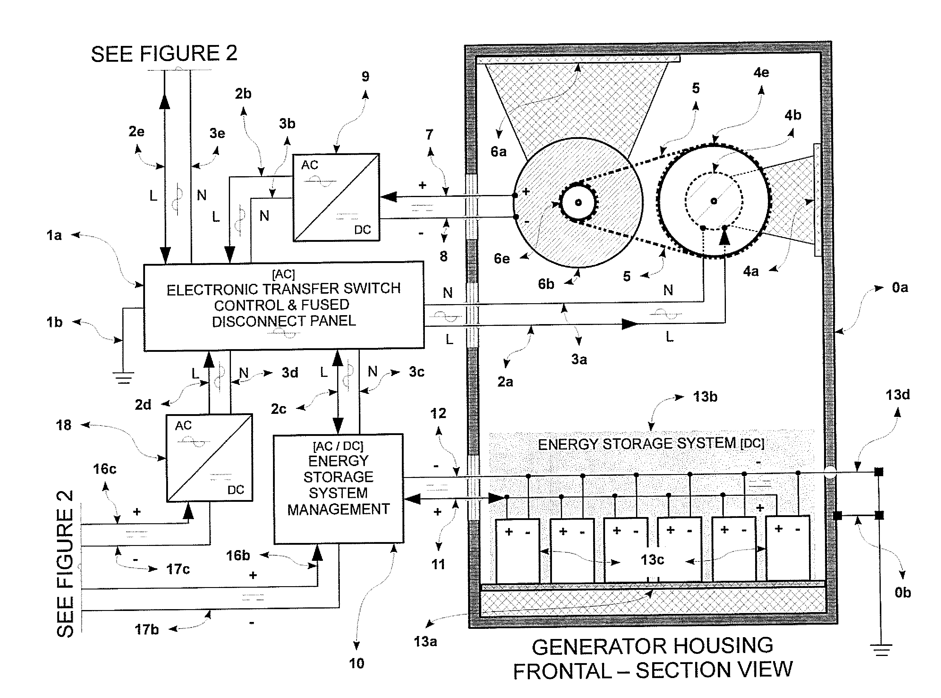
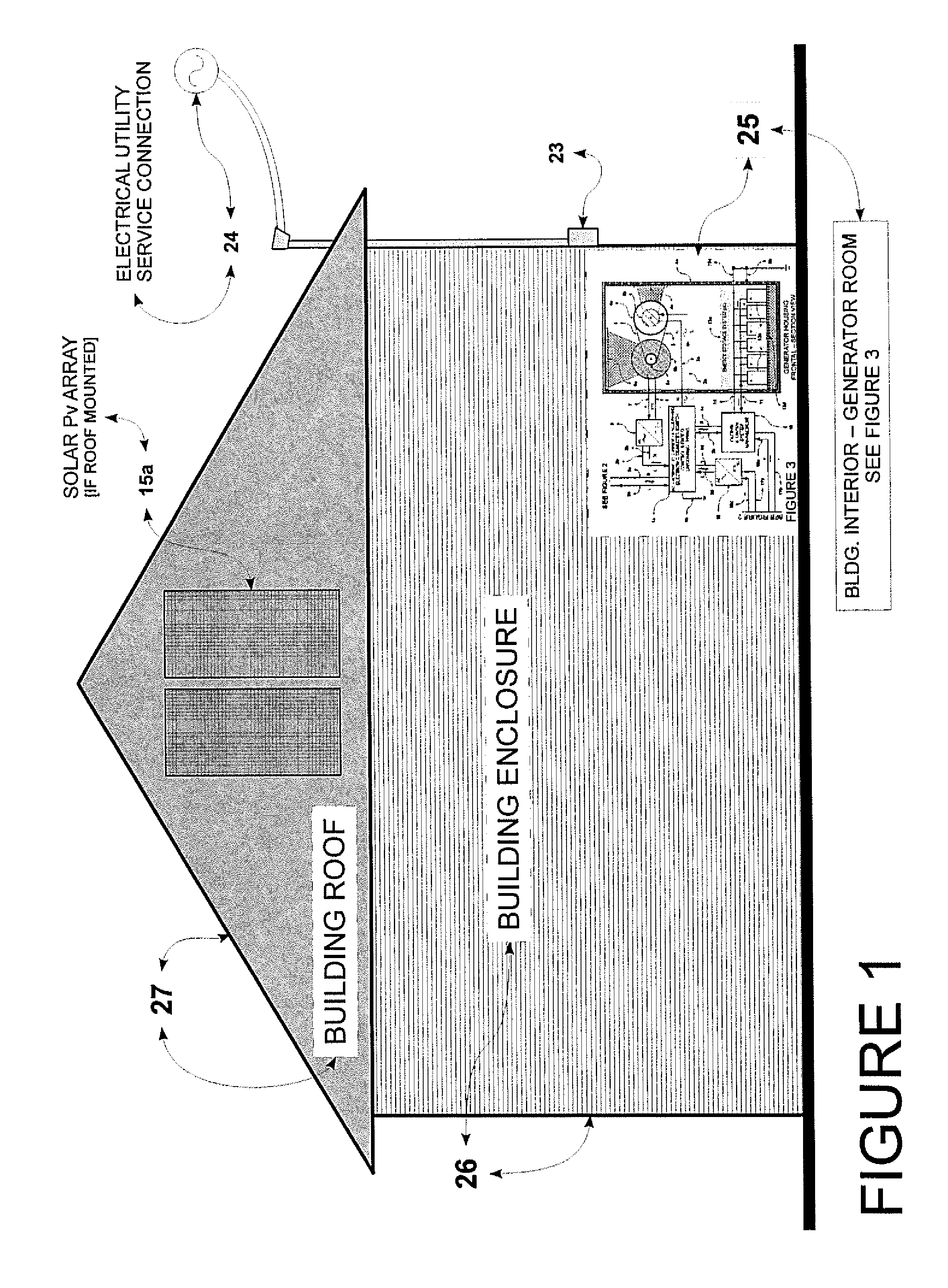
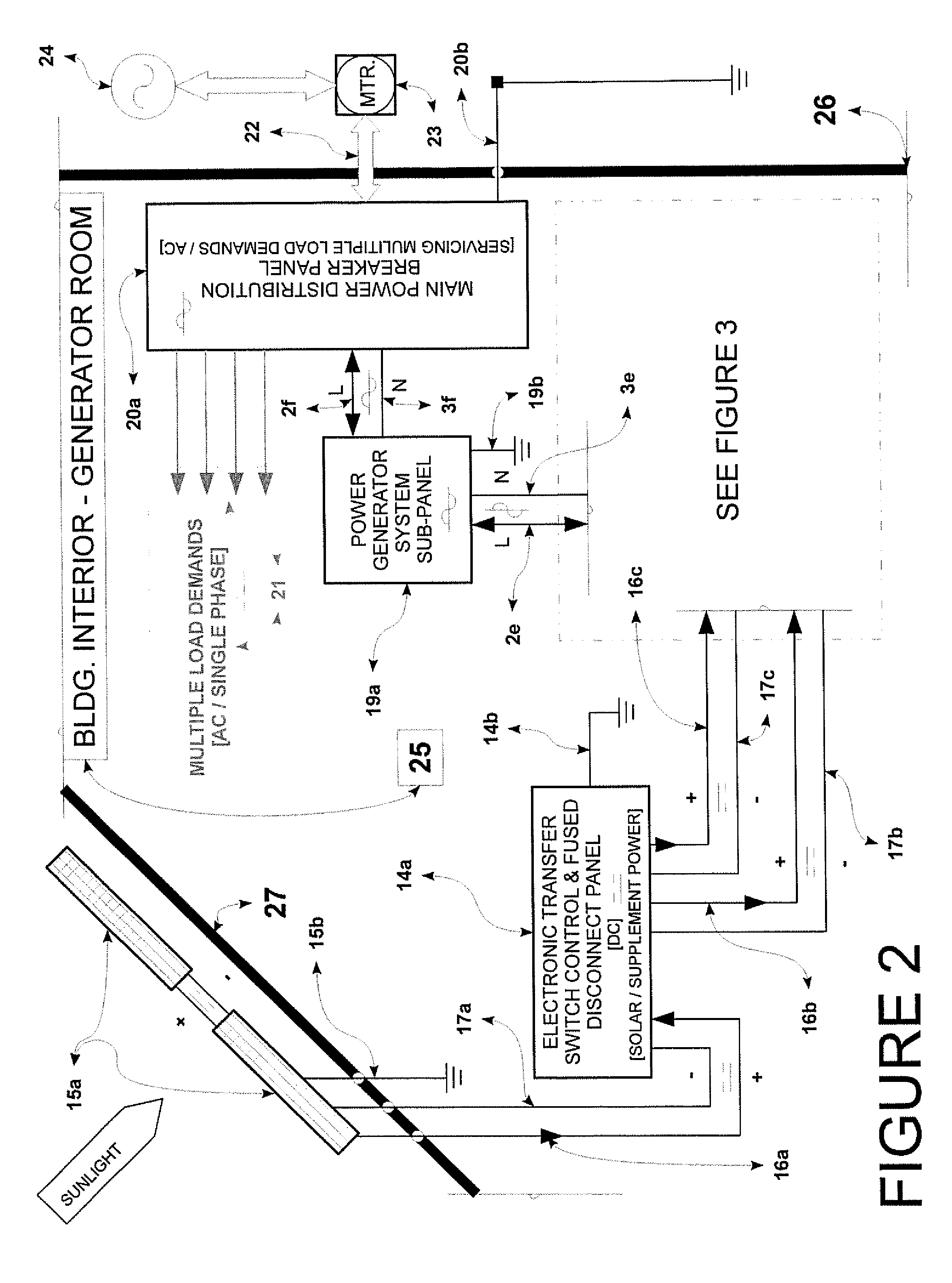
[0021]The regenerative power supply system and method of the present invention is designed to be a principal source of electricity generation to supplant dependence on a local electrical utility. Additionally, solar energy harvested by a solar photovoltaic array is used in the present invention as a backup power supply to the electricity produced by the dynamo-electric generator, thereby mediating the supply of energy from the system and bolstering its stand-alone potential as a distributed power source that may be independent of the gri...


PUM


Abstract

A regenerative power supply system and method comprises a dynamo-electric generator, an electric drive motor coupled to the generator, a transmission device coupling the generator to the electric drive motor, and an energy storage device configured to provide a backup power supply to the regenerative power supply system. An electronic control device is configured to control a flow of electricity to the electric drive motor. An energy storage management device is configured to control a flow of electricity between the electronic control device and the energy storage device.

Description

CROSS-REFERENCES TO RELATED APPLICATIONS[0001]U.S. Provisional Patent Application No. 61 / 779,648STATEMENT REGARDING FEDERALLY SPONSORED RESEARCH OR DEVELOPMENT[0002]Not ApplicablePARTIES TO A JOINT RESEARCH AGREEMENT[0003]Not ApplicableFIELD OF THE INVENTION[0004]This invention is directed generally to electrical power generation, storage and transmission systems and methods and, more particularly, to an electrical power generation, storage and transmission system and a method for supplying power continuously to meet load demands on-site, provide surplus power to a local electrical utility system grid, and / or maintain a stand-alone power supply and storage system isolated from an electrical utility system grid.BACKGROUND[0005]Typically, on-site power generation or energy storage tends to be designed for use only as a backup energy source in the event of the disruption of supply from a normal source of electricity such as a local electrical utility. Those methods may take the form of...

Claims


Application Information

Patent Timeline
Patent Type & Authority Applications(United States)
IPC IPC(8): H02K47/00
CPCH02K47/00Y10S74/09H02K53/00H02J3/32H02J7/1415H02J7/35H02J2310/12H02J2300/24H02J3/381Y02E10/56Y02E10/76Y02E70/30H02K7/14H02K7/1846H02K47/02H02M7/44H02P27/06
Inventor THOMPSON, BARRY
Owner CONSTRUCTIVE IND
Why Eureka
Try Eureka