Microwave acoustic wave filters

a technology of acoustic wave filters and microwaves, applied in the field of microwave filters, can solve the problems of large loss, high insertion loss, and limited basic architecture of aw ief filter designs

Active Publication Date: 2014-09-18
MURATA MFG CO LTD
View PDF12 Cites 18 Cited by
  • Summary
  • Abstract
  • Description
  • Claims
  • Application Information

AI Technical Summary

Problems solved by technology

In subsequent decades, the quartz ladder design was typically only used for single channel filters due to its extremely narrow bandwidth.
Network synthesis designs began to appear in the 1960s, which permitted a much wider variety of filter circuit designs, but also normally required inductors, which tend to be physically large and lossy compared to capacitors.
These designs suffered from high insertion losses due to transducer losses, allowing uses only at intermediate frequencies—not radio frequencies, and were based on transversal designs, also termed “tapped delay lines.”
Thus, the basic architecture of AW IEF filter designs has been limited to the simple paired resonator architecture and minor alterations to the basic AW ladder design, alterations made “after the fact” to this traditional circuit design.

Method used


Image

  • Microwave acoustic wave filters
  • Microwave acoustic wave filters
  • Microwave acoustic wave filters

Examples


Embodiment Construction

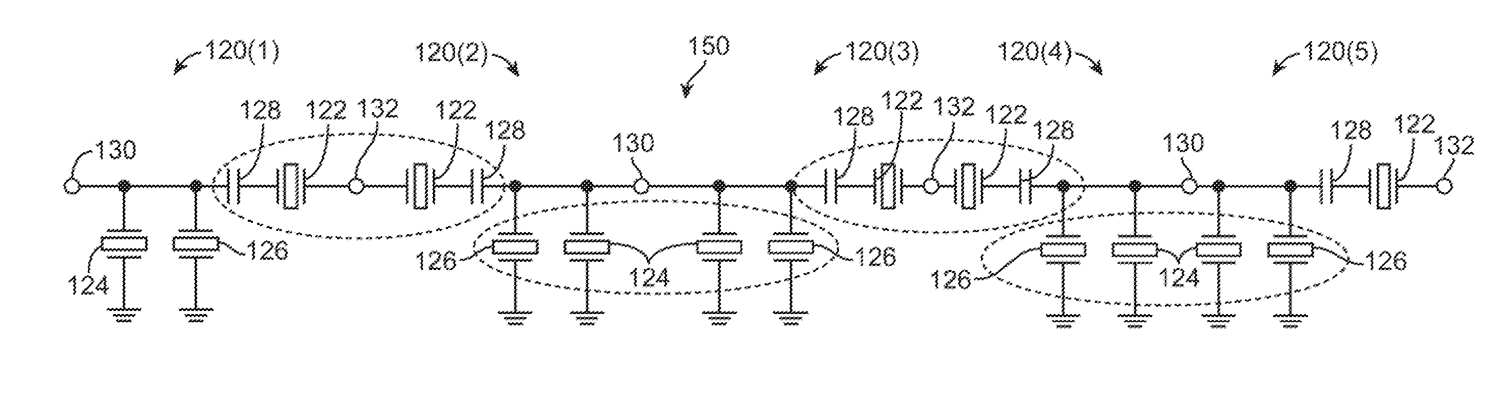
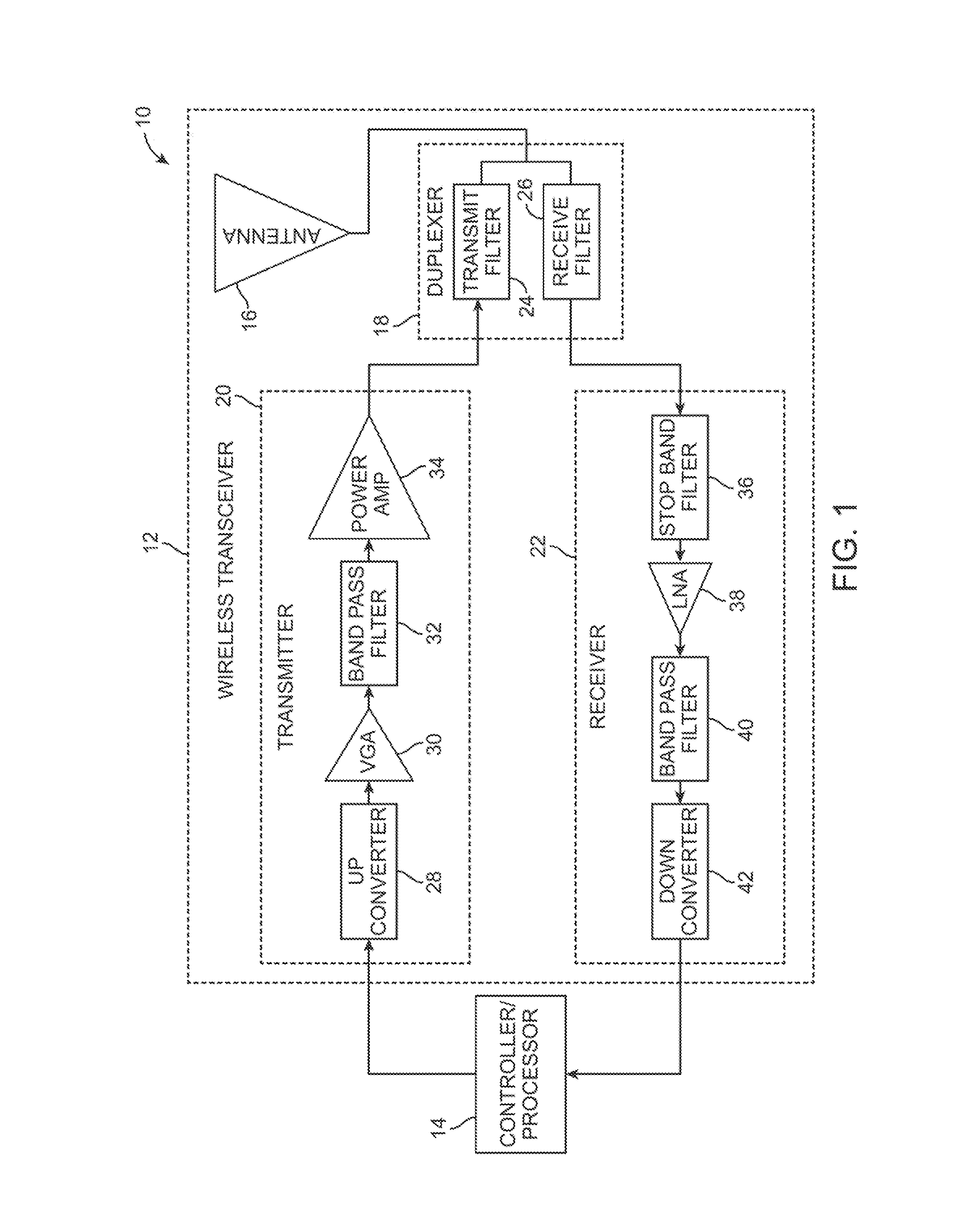
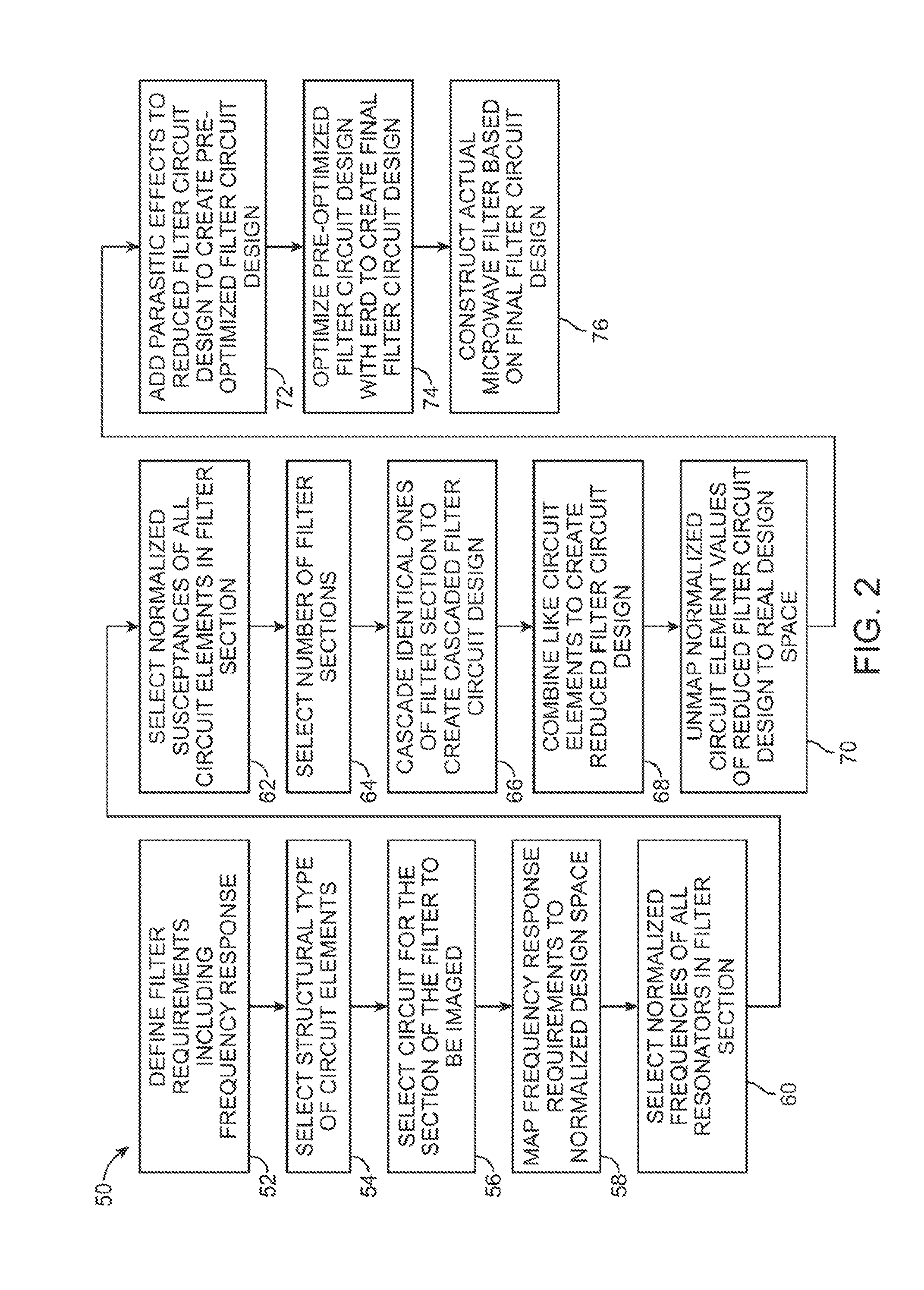
[0034]The present disclosure describes an image technique for designing acoustic wave (AW) microwave filters (such as surface acoustic wave (SAW), bulk acoustic wave (BAW), film bulk acoustic resonator (FBAR), microelectromechanical system (MEMS) filters)). In contrast to the prior art image design techniques, which are limited to the use of a simple paired resonator architecture in each cascaded section of the filter design, the image design technique described herein uses a more complex circuit element architecture in each cascaded section of the filter design. The increased design complexity enabled by this image design technique can lead to designs with improved performance, such as improved insertion loss, improved rejection and / or lower cost.

[0035]The AW microwave filter described herein exhibits a frequency response with a single passband and a single stopband, which is particularly useful in telecommunication system duplexers where a passband with a closely spaced stopband i...


PUM


Abstract

An acoustic microwave filter comprises an input and an output, and a plurality of acoustic resonators coupled between the input and the output. The difference between the lowest resonant frequency and the highest resonant frequency of a plurality of resonators in the filter is at least 1.25 times the frequency separation of the resonator with the highest resonant frequency in the plurality of resonators. Another acoustic microwave filter comprises an input and an output, and a plurality of acoustic resonators coupled between the input and the output to form a passband. The frequency difference between a local minimum or a local maximum of a return loss magnitude of the acoustic microwave filter and the edge of the passband is at least once the frequency separation of the resonator with the highest resonant frequency.

Description

RELATED APPLICATION DATA[0001]The present application claims the benefit under 35 U.S.C. §119 to U.S. provisional patent application Ser. No. 61 / 798,482, filed Mar. 15, 2013. The foregoing application is hereby incorporated by reference into the present application in its entirety.FIELD OF THE INVENTION[0002]The present inventions generally relate to microwave filters, and more particularly, to acoustic wave microwave filters.BACKGROUND OF THE INVENTION[0003]Frequency selective electrical signal filters for communications applications were developed beginning around 1910, for telegraphy and telephony uses, particularly for multiplexing and de-multiplexing of communication signal channels carried on long distance cables and wireless links. Filter design methods, named “image” or “image parameter” design methods were developed by Bell Laboratories, among others, in the 1920s (see George A. Campbell, Physical Theory of the Electric Wave Filter, The Bell System Technical Journal, Volume...

Claims


Application Information

Patent Timeline
Patent Type & Authority Applications(United States)
IPC IPC(8): H03H9/25H03H9/64H03H9/54
CPCH03H9/465H03H9/542H03H9/568G06F17/5063H03H9/6483H03H2260/00H03H9/25H03H9/605H03H9/462H03H9/64G06F30/36H03H9/54H03H9/56H03H9/60G06F30/00
Inventor SILVER, RICHARD N.RAIHN, KURT F.FENZI, NEAL O.HAMMOND, ROBERT B.
Owner MURATA MFG CO LTD
Why Eureka
Try Eureka