
Topography minimization of neutral layer overcoats in directed self-assembly applications

a technology of neutral layer and directed self-assembly, which is applied in the direction of photomechanical equipment, photosensitive material processing, instruments, etc., can solve the problems of easy induced defects and line-edge roughness, increased defects, and negative chemo-epitaxy effects on dimension control and line-edge roughness

Active Publication Date: 2014-09-18
TOKYO ELECTRON LTD
View PDF4 Cites 67 Cited by
  • Summary
  • Abstract
  • Description
  • Claims
  • Application Information

AI Technical Summary

Benefits of technology

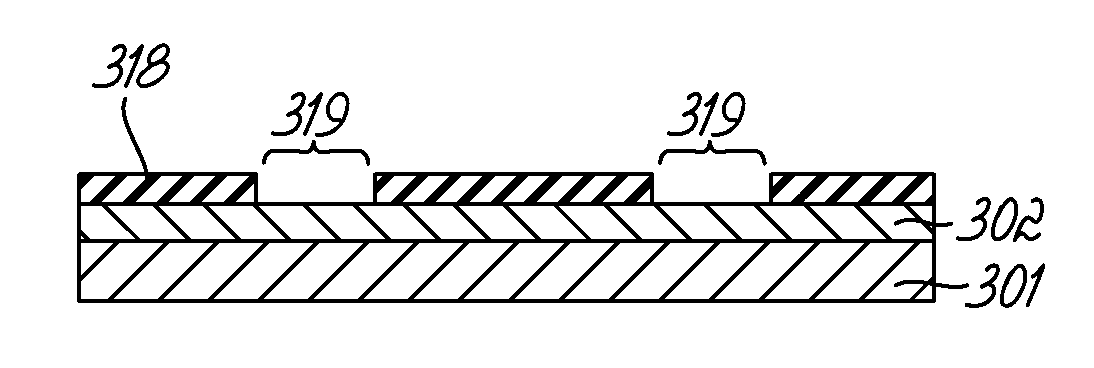
The present invention provides a method for patterning a layered substrate in directed self-assembly applications. The method includes coating the substrate with a photoresist material, patterning the photoresist material layer to form a pattern, and transferring the substrate to a deposition processing system. A neutral layer is then deposited over the pattern and exposed portions of the substrate. The photoresist pattern can be hardened or trimmed, and a DSA material layer is deposited over the neutral layer template to form a pattern which can be developed for subsequent etching. This method has improved precision and accuracy in patterning, and can be used in various directional self-assembly applications.

Problems solved by technology

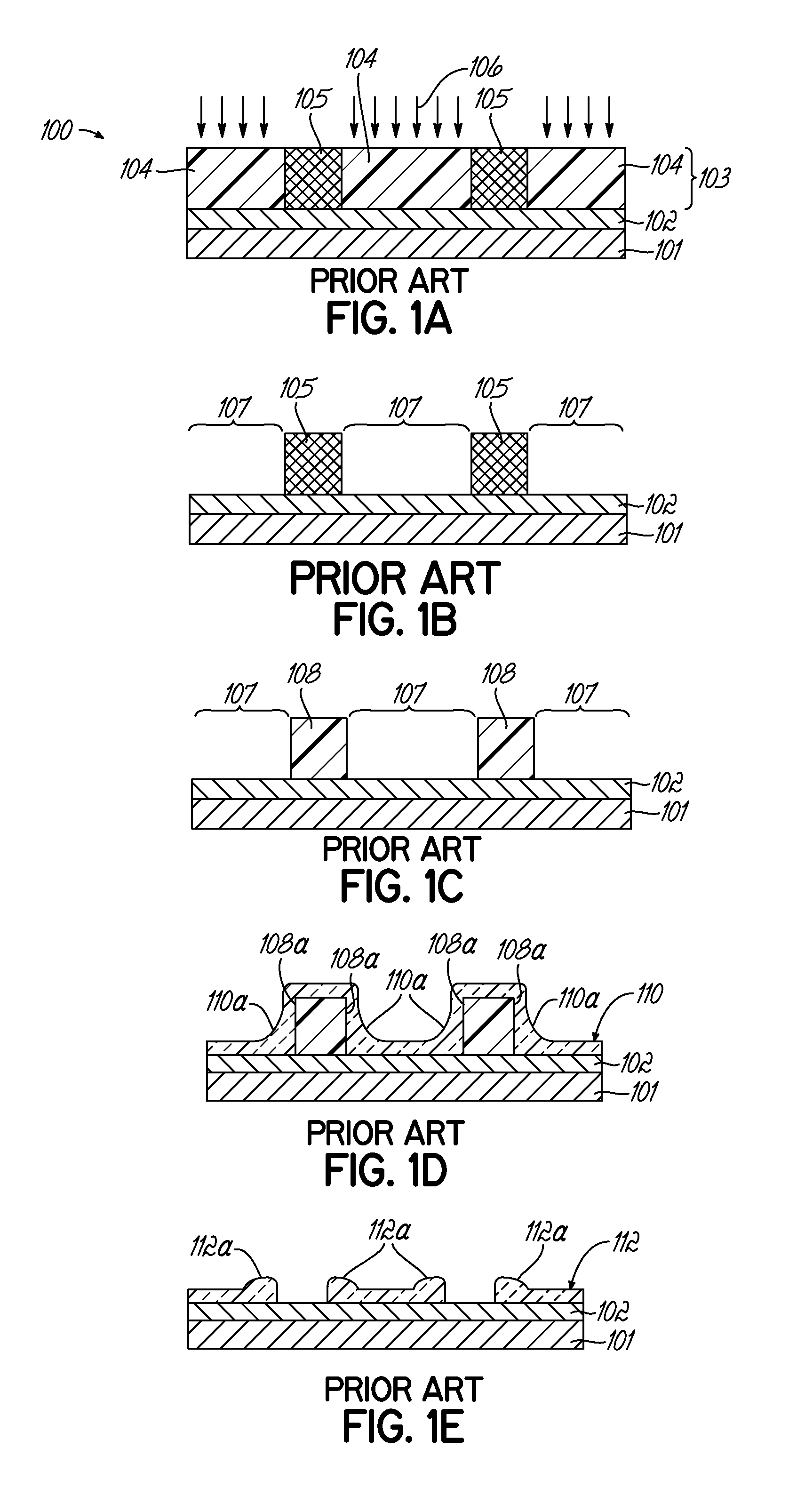
However, defects and line-edge roughness are easily induced in this grapho-epitaxy directed self-assembly scheme.
However, dimension control and line-edge roughness can be negatively affected in chemo-epitaxy methods by topographical variations in the chemical pre-pattern.
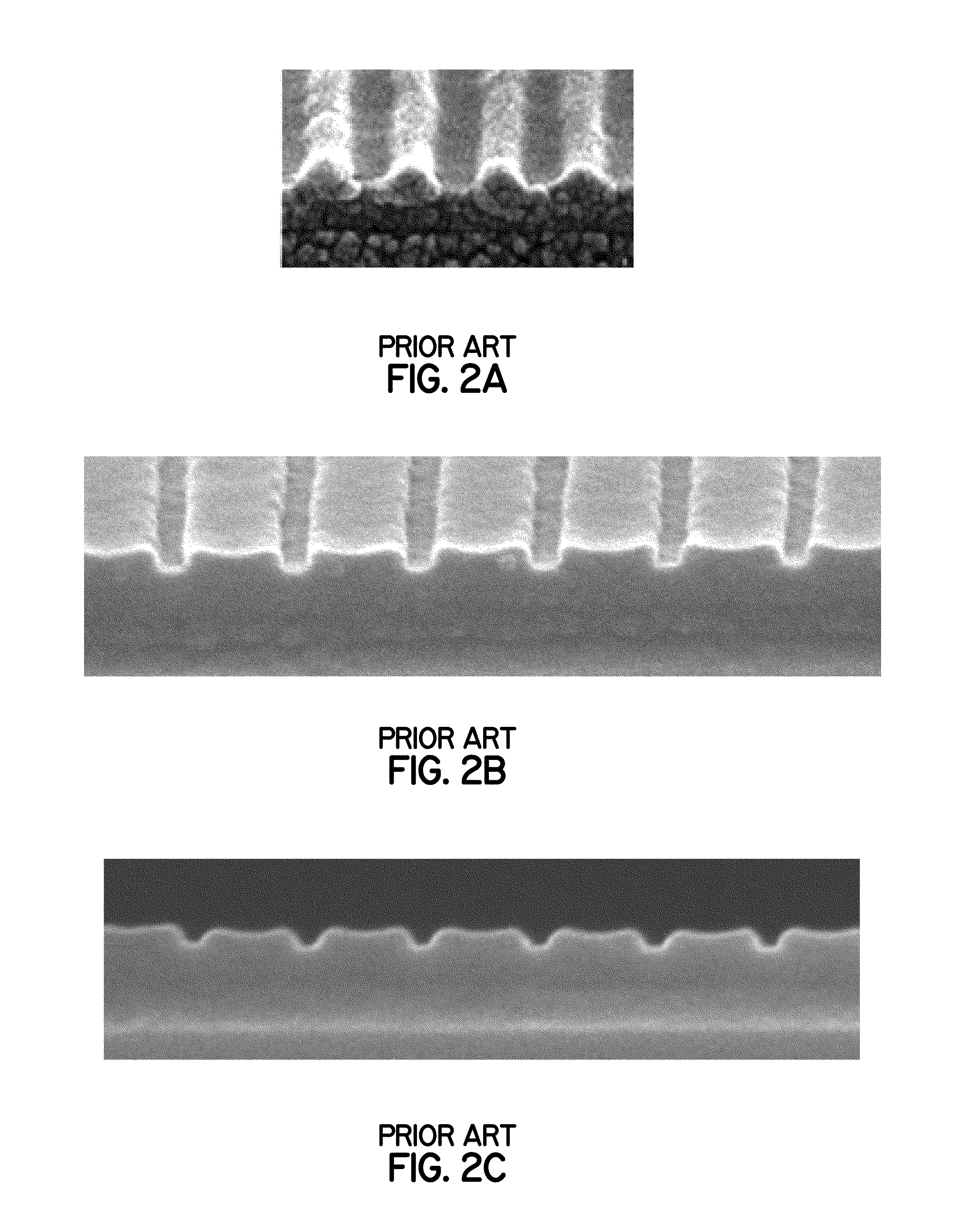
The increased variations in neutral layer topography can lower the propensity of an overlying layer of BCP to undergo DSA, which in turn causes an increase in defects.

Method used


Image

  • Topography minimization of neutral layer overcoats in directed self-assembly applications
  • Topography minimization of neutral layer overcoats in directed self-assembly applications
  • Topography minimization of neutral layer overcoats in directed self-assembly applications

Examples


Embodiment Construction

[0022]Methods for forming a prepattern to be used with direct self-assembly (“DSA”) integrations are disclosed in various embodiments. However, one skilled in the relevant art will recognize that the various embodiments may be practiced without one or more of the specific details or with other replacement and / or additional methods, materials, or components. In other instances, well-known structures, materials, or operations are not shown or described in detail to avoid obscuring aspects of various embodiments of the present invention.

[0023]Similarly, for purposes of explanation, specific numbers, materials, and configurations are set forth in order to provide a thorough understanding. Nevertheless, the embodiments of the present invention may be practiced without specific details. Furthermore, it is understood that the illustrative representations are not necessarily drawn to scale.

[0024]Reference throughout this specification to “one embodiment” or “an embodiment” or variation ther...


PUM

PropertyMeasurementUnit
Chemical propertiesaaaaaaaaaa
Electrical resistanceaaaaaaaaaa

Abstract

A method is provided for patterning a layered substrate that includes loading a substrate into a coater-developer processing system; coating the substrate with a photoresist material layer; patterning the photoresist material layer to form a photoresist pattern; transferring the substrate to a deposition processing system; and depositing a neutral layer over the photoresist pattern and exposed portions of the substrate. The neutral layer can deposited using a gas cluster ion beam (GCIB) process, or an atomic layer deposition (ALD) process, which has minimal topography. The method may further include lifting off a portion of the neutral layer deposited over the photoresist pattern to expose a neutral layer template for subsequent directed self-assembly (DSA) patterning; depositing a DSA material layer over the neutral layer template; baking the DSA material layer to form a DSA pattern; and developing the DSA material layer to expose the final DSA pattern for subsequent feature etching.

Description

CROSS REFERENCE TO RELATED APPLICATION[0001]Pursuant to 37 C.F.R. §1.78(a)(4), this application claims the benefit of and priority to prior filed co-pending Provisional Application No. 61 / 782,518 filed Mar. 14, 2013, which is expressly incorporated herein by reference.FIELD OF THE INVENTION[0002]The present invention is directed to a patterning process using directed self-assembly.BACKGROUND OF THE INVENTION[0003]Directed self-assembly (“DSA”) processes use block copolymers to form lithographic structures, which are formed by the rearrangement of the block copolymer from a random, unordered state to a structured, ordered state. The morphology of the ordered state is variable and depends on a number of factors, including the relative molecular weight ratios of the block polymers, as well as the surrounding chemical and physical environment. Common morphologies include line-space and cylindrical, although other structures may also be used. For example, other ordered morphologies inclu...

Claims


Application Information

Patent Timeline
IPC IPC(8): H01L21/033
CPCH01L21/0337H01L21/0271B82Y10/00B82Y40/00C23C14/221C23C16/45525G03F7/0002G03F7/40G03F7/405H01J37/317H01L21/0272
Inventor SOMERVELL, MARK H.RATHSACK, BENJAMEN M.
Owner TOKYO ELECTRON LTD
Learn More