
Cable module connector assembly suitable for use in blind-mate applications

a technology of connectors and cable modules, applied in the direction of electrical apparatus, coupling device connections, printed circuits, etc., can solve the problems of large insertion force of assembly of the present disclosure, and achieve the effect of high insertion force and easy overcomemen

Inactive Publication Date: 2014-09-18
MOLEX INC
View PDF15 Cites 65 Cited by
  • Summary
  • Abstract
  • Description
  • Claims
  • Application Information

AI Technical Summary

Benefits of technology

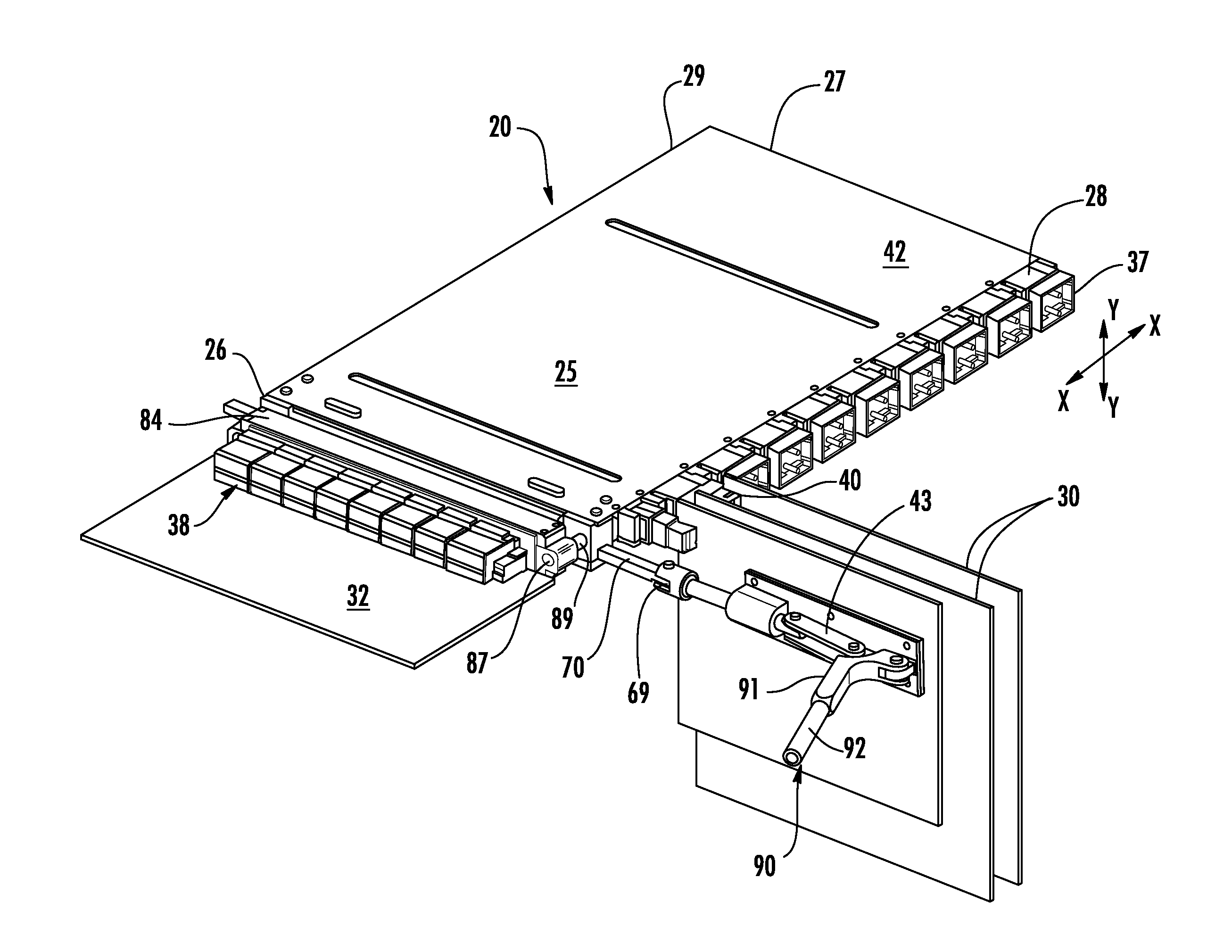
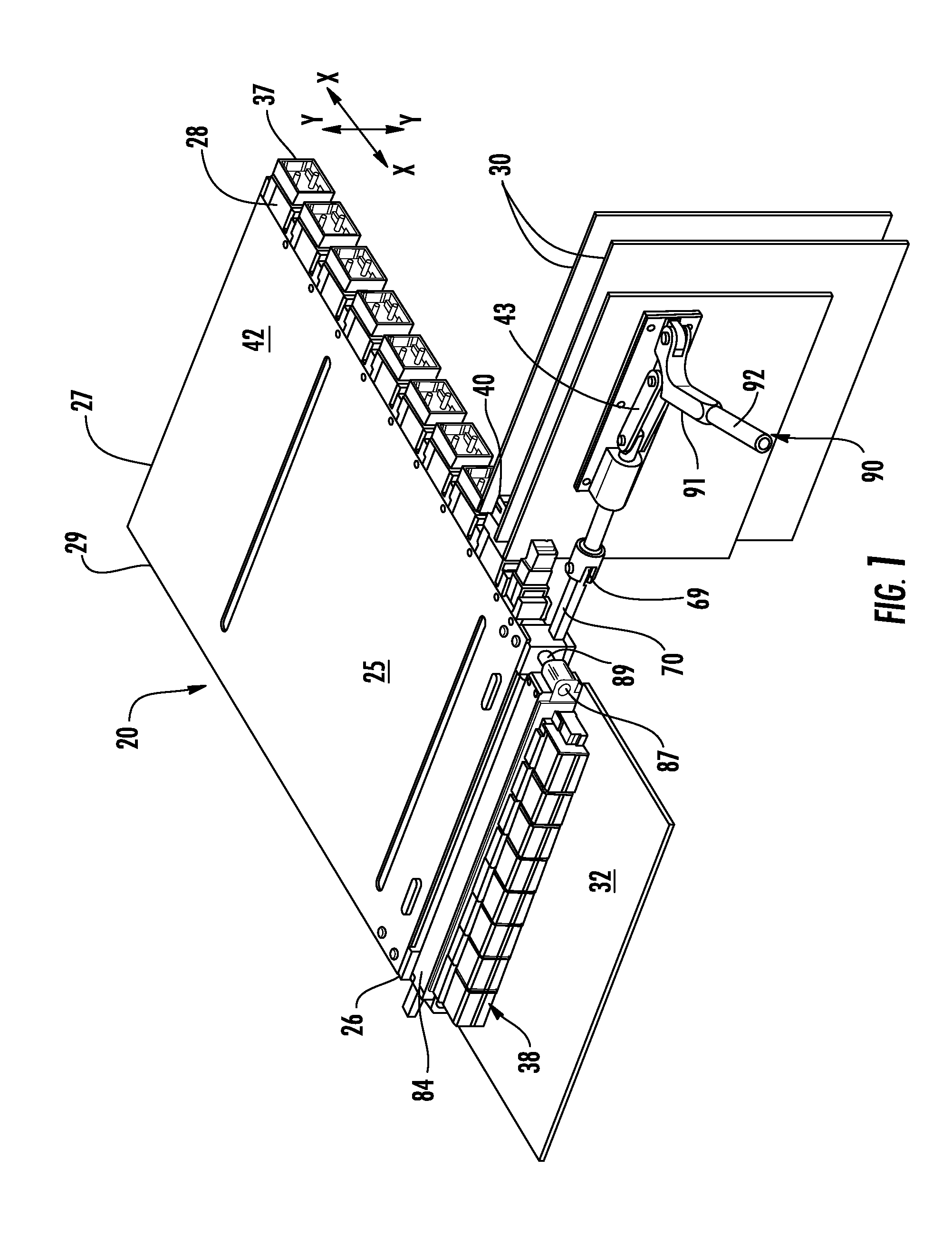
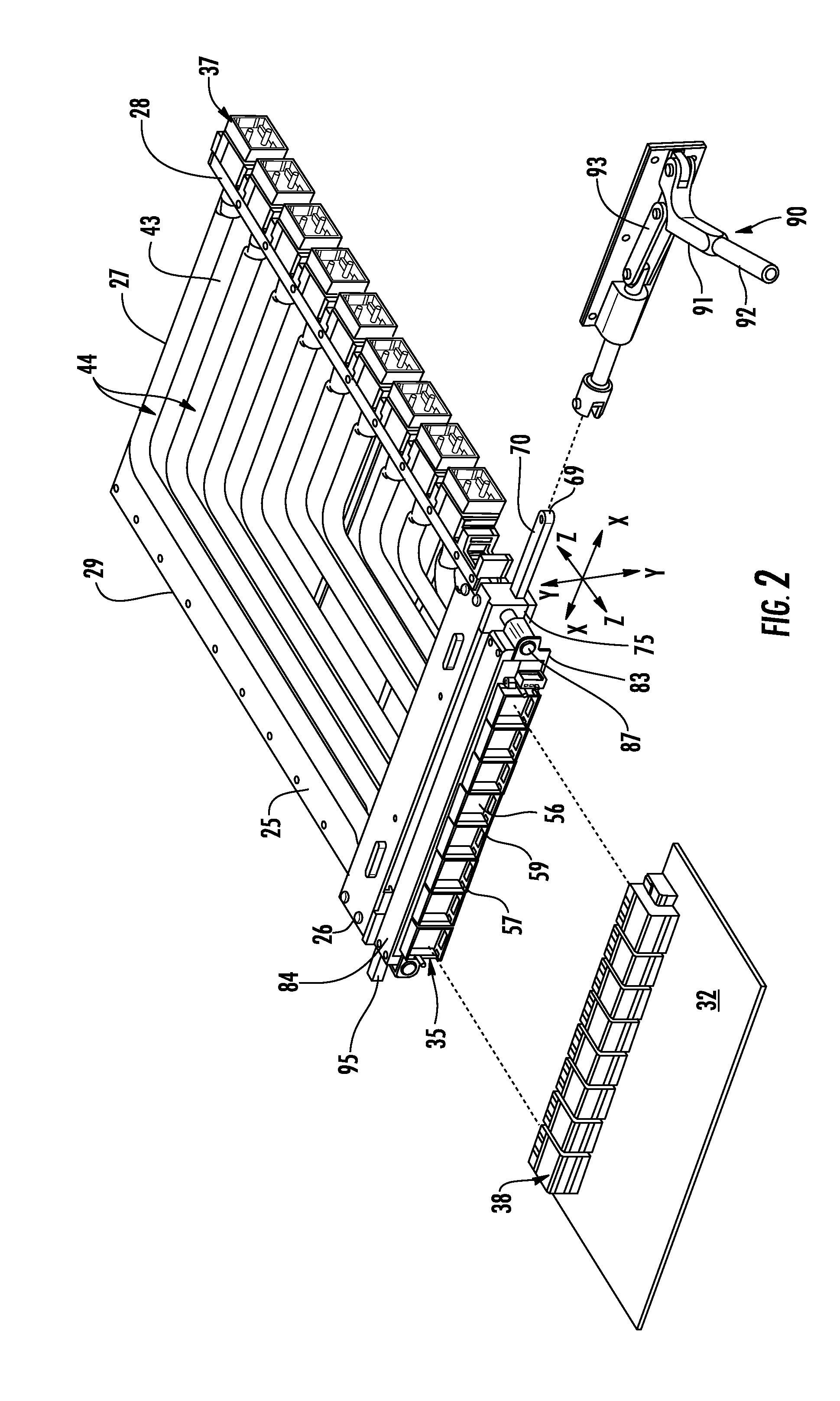
The patent describes a cable module assembly that has a high density of connectors and requires a large insertion force to mate with opposing connectors. To reduce the force required to operate the actuator, an exterior actuator with a large mechanical advantage can be utilized. The module has a carrier that holds the connectors and allows them to move in a flexible manner. The actuator mechanism includes a lever that engages an actuating shaft and a drawbar that rides along cam slots in the slide housing to move the connectors into mating contact with opposing connectors. The actuator can be easily operated with a crank or a linkage mechanism. The use of cables to interconnect the connector sets simplifies the assembly and eliminates the need for a complex connection between the circuit board and the connector sets.

Problems solved by technology

Consequently, the connector assemblies of the Present Disclosure require a large insertion force.

Method used


Image

  • Cable module connector assembly suitable for use in blind-mate applications
  • Cable module connector assembly suitable for use in blind-mate applications
  • Cable module connector assembly suitable for use in blind-mate applications

Examples


Embodiment Construction

[0033]While the Present Disclosure may be susceptible to embodiment in different forms, there is shown in the Figures, and will be described herein in detail, specific embodiments, with the understanding that the Present Disclosure is to be considered an exemplification of the principles of the Present Disclosure, and is not intended to limit the Present Disclosure to that as illustrated.

[0034]As such, references to a feature or aspect are intended to describe a feature or aspect of an example of the Present Disclosure, not to imply that every embodiment thereof must have the described feature or aspect. Furthermore, it should be noted that the description illustrates a number of features. While certain features have been combined together to illustrate potential system designs, those features may also be used in other combinations not expressly disclosed. Thus, the depicted combinations are not intended to be limiting, unless otherwise noted.

[0035]In the embodiments illustrated in ...


PUM


Abstract

A cable module that utilizes a plurality of multi-wire cables to provide connections between two sets of connectors is disclosed. The module has a first set of connectors intended to mate with mating connectors disposed on a mother board and a second set of connectors intended to mate with a plurality of opposing connectors disposed on a plurality of daughter boards. The mother board generally lies in the same plane as the base of the module, while the daughter boards are oriented generally transverse to the module base. The two sets of connectors are capable of limited movement in the horizontal and vertical directions to give the module assembly blind mate functionality. The second set of connectors is restricted from movement in the depth direction, while the first set of connectors is capable of such movement. An exterior actuating mechanism provides a mechanical advantage that reduces the effort required to advance the first set of connectors into mating engagement with their opposing counterparts on the mother board.

Description

BACKGROUND OF THE PRESENT DISCLOSURE[0001]The Present Disclosure relates generally to high-insertion force connectors, and, more particularly, to high-insertion force connectors used within minimal space environments, such as blind mate environments.[0002]In the current environment of high-speed data transmission, it is desirable to have high speeds and maximum density. Although this has been done before in terms of data transmission lines supported by circuit boards, it becomes problematic to run circuit board traces on a circuit board and not encounter impedance problems, noise, crosstalk and the like, especially at speeds exceeding 5 Gbs per second. The use of cables as a bypass to circuit board circuits has recently been adopted. However, each cable is usually terminated to a single connector. A cable with a large number of signal transmission wire pairs requires a connector with a large number of terminals to mate with an opposing connector. The use of pins as the connector ter...

Claims


Application Information

Patent Timeline
IPC IPC(8): H01R12/73H01R12/72
CPCH01R12/727H01R12/737H01R13/631H01R31/005
Inventor RESENDEZ, JAVIERKEYSER, FRANK T.LAURX, JOHN
Owner MOLEX INC
Learn More