CPR Gurney
- Summary
- Abstract
- Description
- Claims
- Application Information
AI Technical Summary
Benefits of technology
Problems solved by technology
Method used
Image
Examples
Embodiment Construction
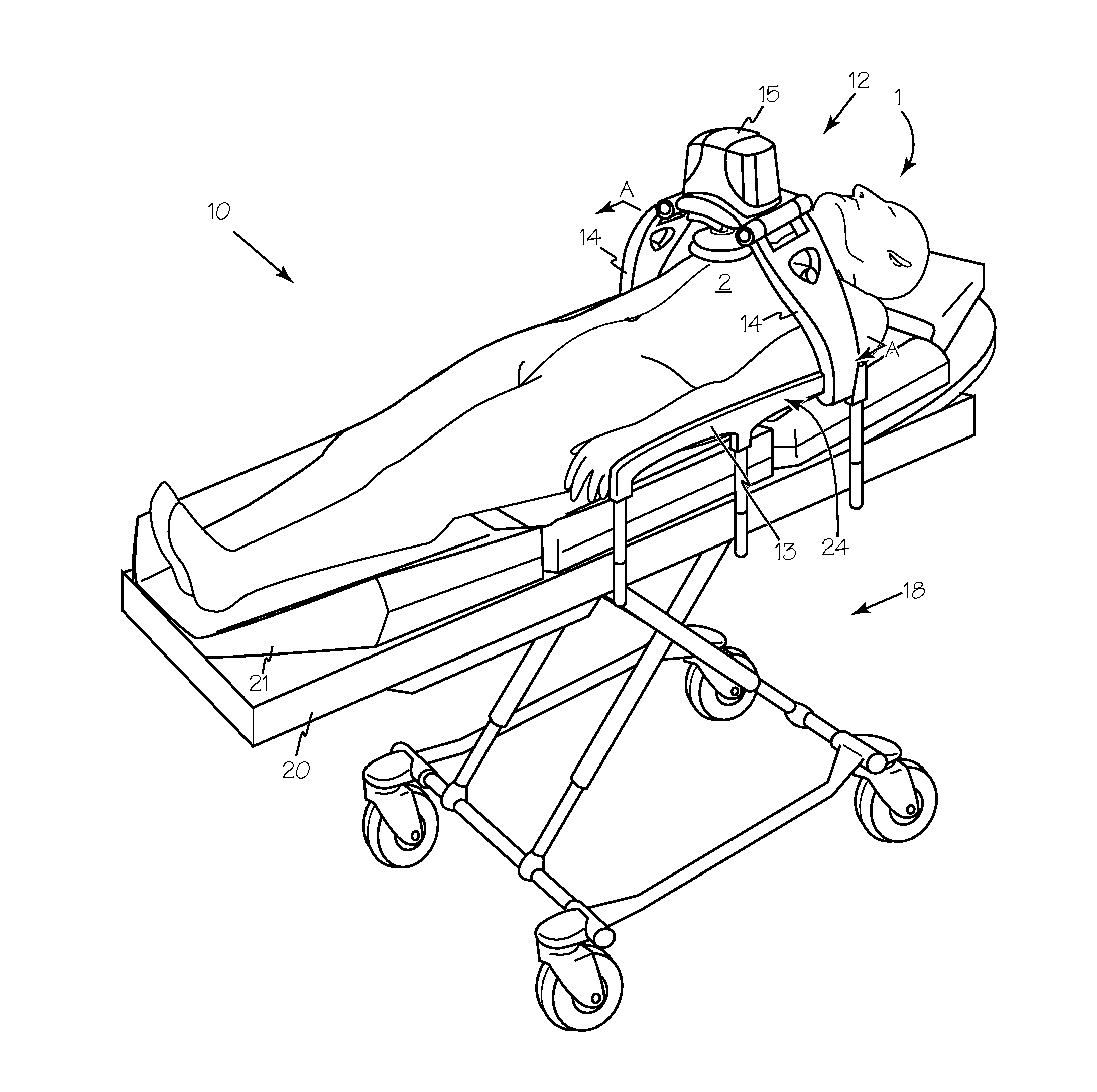
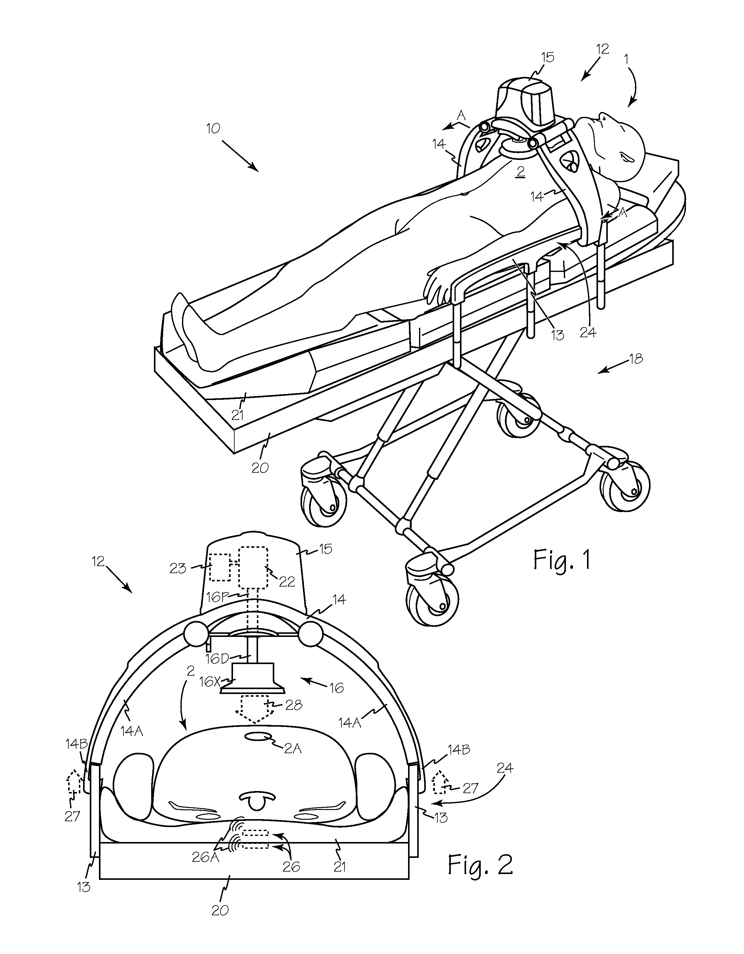
[0023]FIG. 1 is a perspective view of supine patient 1 on transport gurney 10 with piston driven chest compression device 12 engaging side rails 13. FIG. 2 is a cross-section view of the gurney and patient of FIG. 1 taken along A-A showing landmark skeletal structures. Chest compression device 12 is oriented to apply compressions to the chest 2 of patient 1 while the patient is supported in transport gurney 10. Chest compression device 12 includes support structure or legs 14 which supports and orients chest compression unit 15 and plunger 16 apposing sternum 2A. Transport gurney 10 includes any suitable wheeled support frame 18 supporting a table, support platform or deck such as deck 20 and movably engaging side rails such a side rails 13. Transport gurney 10 may also include a suitable mattress, cushion or pad such as pad 21.
[0024]Chest compression unit 15 includes any suitable drive means such as motor 22 which may be an electromotor, a hydraulic motor, a linear, pneumatic or hy...
PUM
 Abstract
Description
Claims
Application Information
 - R&D Engineer
- R&D Manager
- IP Professional
- Industry Leading Data Capabilities
- Powerful AI technology
- Patent DNA Extraction
Browse by: Latest US Patents, China's latest patents, Technical Efficacy Thesaurus, Application Domain, Technology Topic, Popular Technical Reports.
© 2024 PatSnap. All rights reserved.Legal|Privacy policy|Modern Slavery Act Transparency Statement|Sitemap|About US| Contact US: help@patsnap.com


