Mattress System

a mattress and mattress technology, applied in the field of mattress systems, can solve the problems of increased aging rate and the risk of a compressor malfunction, the response of the sensor pad is not sharp enough, and the risk of additional components malfunctioning, etc., and achieves good elasticity

Inactive Publication Date: 2014-09-25
SHL GRP AB
View PDF13 Cites 29 Cited by
  • Summary
  • Abstract
  • Description
  • Claims
  • Application Information

AI Technical Summary

Benefits of technology

[0007]In view of the shortcomings of the conventional mattress systems described in the above, an object of the present invention is to provide a mattress system having a simple structure and utilizing a unique user interface such as a turning knob mounted on a control unit to adjust three major system functions (namely, therapy mode, therapy intensity level, and comfort level) at the same time. The mattress system in accordance with the present invention is further provided with an auto-setting process, which is a requisite for the mattress system and used to detect body characteristics of a patient lying on the mattress and determine an effective supporting pressure range for the patient, such that the mattress system can always provide the patient not only a suitable therapeutic pressure support, but also an adjustable comfort feeling.
[0015]There is provided a mattress system in accordance with the present invention, wherein an operation process is respectively performed in the therapy mode so as to obtain a lowest supporting pressure required for the patient whose body characteristics have been sensed in the static therapy mode, and a lowest inflated supporting pressure required for the patient whose body characteristics have been sensed in the alternating therapy mode, such that a promised therapeutic effect can be achieved.
[0024]There is provided a mattress system in accordance with the present invention, further comprising an active coverlet provided to be covered on the mattress as an interface between the patient's body and the mattress so as to control the removal of excessive heat and moisture from a contact surface between the patient's body and the mattress.
[0029]There is provided a mattress system in accordance with the present invention, wherein the middle layer formed with a three-dimensional porous structure is placed within an enclosure as an air channel to allow the air to be flowed within the enclosure, and has a good elasticity under compression.

Problems solved by technology

However, limitations of the U.S. Pat. No. 6,928,681 are that a constant loss of air from the mattress system and a continuous operation of a compressor with a higher capacity, which increase the rate of aging and the risk of a malfunction of the compressor.
Placing the sensor pad under the mattress will cause the response of the sensor pad to be not sharp enough.
Another disadvantage is that the mattress system requires more additional components, which greatly increases the manufacture cost and the risk of the malfunction of the additional components.
There is still another disadvantage that the mattress system only provides an alternating mode with respect to the system therapy modes, which causes that the therapeutic effect, is inferior.
However, a constant bleeding of fluid from the sensor pad, which causes a waste of energy, and a challenge in the lifetime and the risk of a malfunction of the compressor are still required.
An extended use of the sensor pad to cover the entire mattress allows the control to the head and leg zones, but the requirement of additional components causes a higher manufacture cost and increases the risk of the malfunction of the additional components.
Moreover, the mattress system only provides an alternating mode with respect to the system therapy modes, and thus the therapeutic effect is inferior.
However, the mattress system of the C.A. Patent No. 2 567 951 is complicated since additional electrical components are integrated into the mattress, which increases the risk of electrical hazards to the patient lying on the mattress.
The additional components also increase the manufacture cost and the risk of the malfunction of the additional components.
However, the mattress system is inconvenient in use due to a need of switching between these two user panels and is complicated in operation for a caregiver and a patient required for treatment.

Method used


Image

  • Mattress System
  • Mattress System
  • Mattress System

Examples


Embodiment Construction

[0051]Embodiments in accordance with the present invention will be described hereinafter with reference to the accompanying drawings by exemplifying a mattress system.

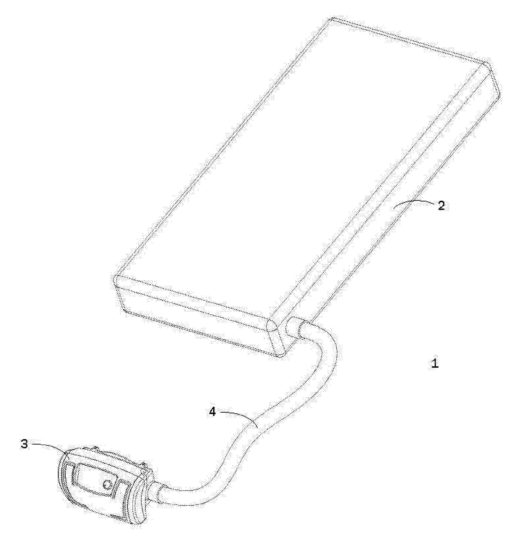
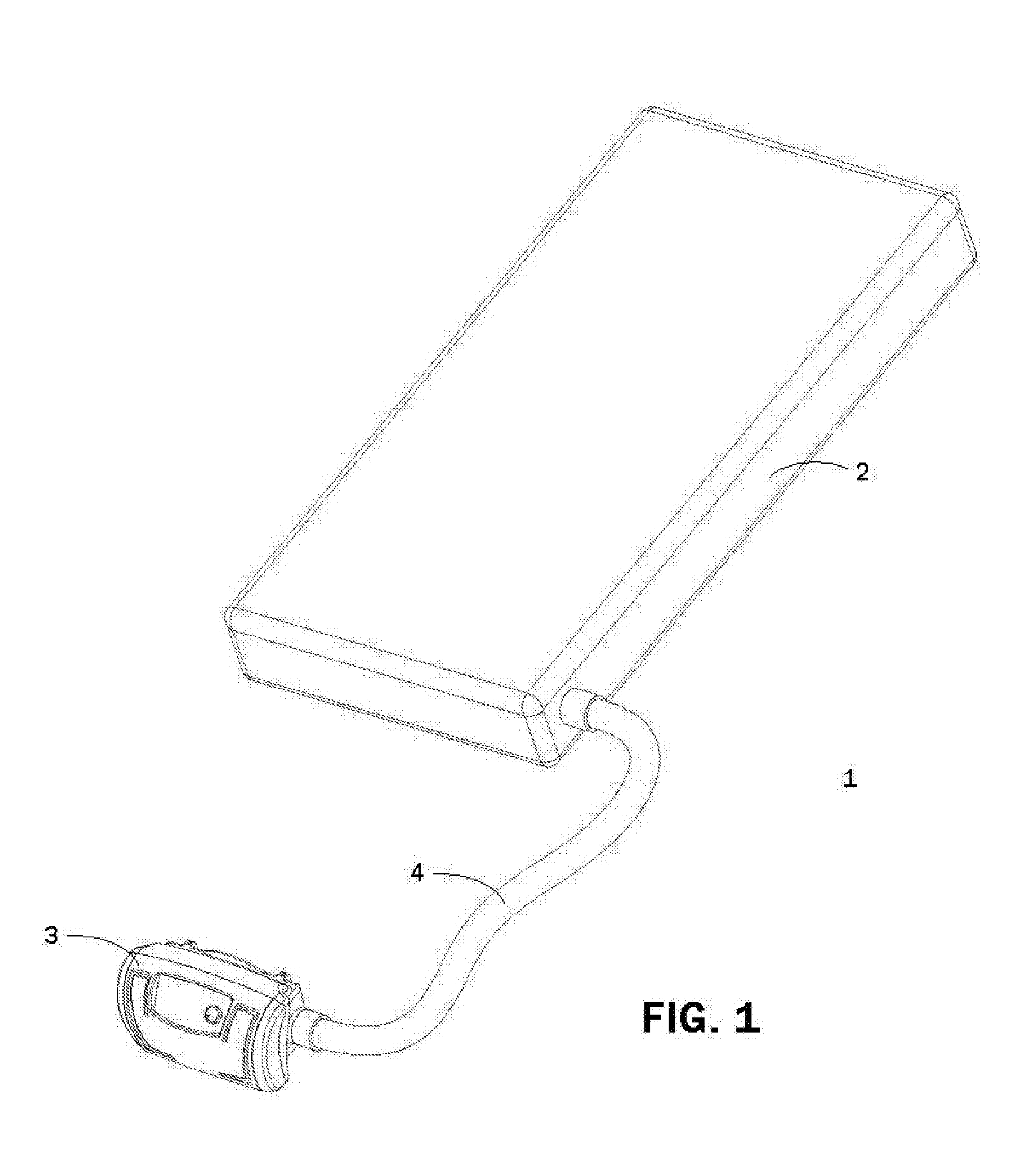
[0052]With reference to FIG. 1, a configuration of the mattress system 1 in accordance with an embodiment of the present invention is explained below.

[0053]FIG. 1 is a schematic perspective view of the mattress system 1 in accordance with an embodiment of the present invention.

[0054]As shown in FIG. 1, the mattress system 1 comprises a mattress 2 used to provide a function of pressure supporting for a patient, a control unit 3 used to control inflation and deflation of the mattress 2, and a connection pipe 4 provided between the mattress 2 and the control unit 3 to supply air and power.

[0055]The control unit 3 is equipped with a user interface 31 (to be described later) such that a caregiver can make a continuous integral adjustment in an aspect of comfort level (also referred to as an effective supporting pressure lev...


PUM


Abstract

A mattress system devised to achieve a function of automatic detection, mainly including a mattress having a simple structure; a control unit equipped with a unique user interface for caregivers to simultaneously adjust three major functions, namely, therapy mode, therapy intensity and comfort level; and a connection pipe for supplying air and power. The system is further provided with a built-in auto-setting function to sense the body characteristics of the patient lying on the mattress and determine an effective supporting pressure range for the patient. By detecting a pressure difference representing the body characteristics of the patient lying on the mattress and comparing with the data stored in a built-in database, the system can always provide the patient with not only a well-proved therapeutic effect through the auto-setting function, but also an adjustable comfort level on the patient's request through the user interface.

Description

FIELD OF THE INVENTION[0001]The present invention relates to a mattress system for medical treatment, and more particularly, to a mattress system provided with an auto-setting process so as to achieve a function of automatic detection of the body characteristics of a patient lying on the mattress.DESCRIPTION OF THE RELATED ART[0002]A mattress system for medical treatment is mainly used for the prevention and treatment of pressure ulcers. The mattress system normally consists of an air pressure source connected to a mattress formed with a series of air cells arranged inside through pipelines, and a pressure sensor for detecting pressure in each zone of the mattress. The pressure level in each zone of the mattress is regulated by controlling dispensing valves through the air pressure source and a controller so as to provide a good blood circulation for a patient lying on the mattress, prevent a portion of the patient's body to be treated being continuously compressed, and supply a sui...

Claims


Application Information

Patent Timeline
Patent Type & Authority Applications(United States)
IPC IPC(8): A61G7/057A61H31/00A61G7/018
CPCA61G7/018A61H31/008A61G7/05776A61G7/05792
Inventor CHEN, HSUEH-YIFENG, WEN-HUNGTU, SHIH-HSUN
Owner SHL GRP AB
Why Eureka
Try Eureka