
Imaging apparatus and method for controlling same

a technology of imaging apparatus and control method, which is applied in the field of imaging apparatus, can solve the problems of reducing the reliability of the signals acquired from the imaging element, imperiling the accuracy of exact focus detection calculation, and affecting the accuracy of the detection of images, etc., and achieves the effect of suppressing the adverse effect of signals and low reliability

Active Publication Date: 2014-09-25
CANON KK
View PDF1 Cites 23 Cited by
  • Summary
  • Abstract
  • Description
  • Claims
  • Application Information

AI Technical Summary

Benefits of technology

The present invention provides an imaging apparatus that can accurately detect focus by using an imaging element with pixel portions that produce a focus detection signal. This is done by suppressing the impact of signals that are not very reliable. The technical effect of this invention is to enable accurate focus detection.

Problems solved by technology

Consequently, signals subjected to pupil division may not be correctly read.
In other words, the reliability of the signals acquired from the imaging element is decreased in a state in which light intensity is greater than a certain level, which may imperil exact focus detecting calculation.

Method used


Image

  • Imaging apparatus and method for controlling same
  • Imaging apparatus and method for controlling same
  • Imaging apparatus and method for controlling same

Examples


Embodiment Construction

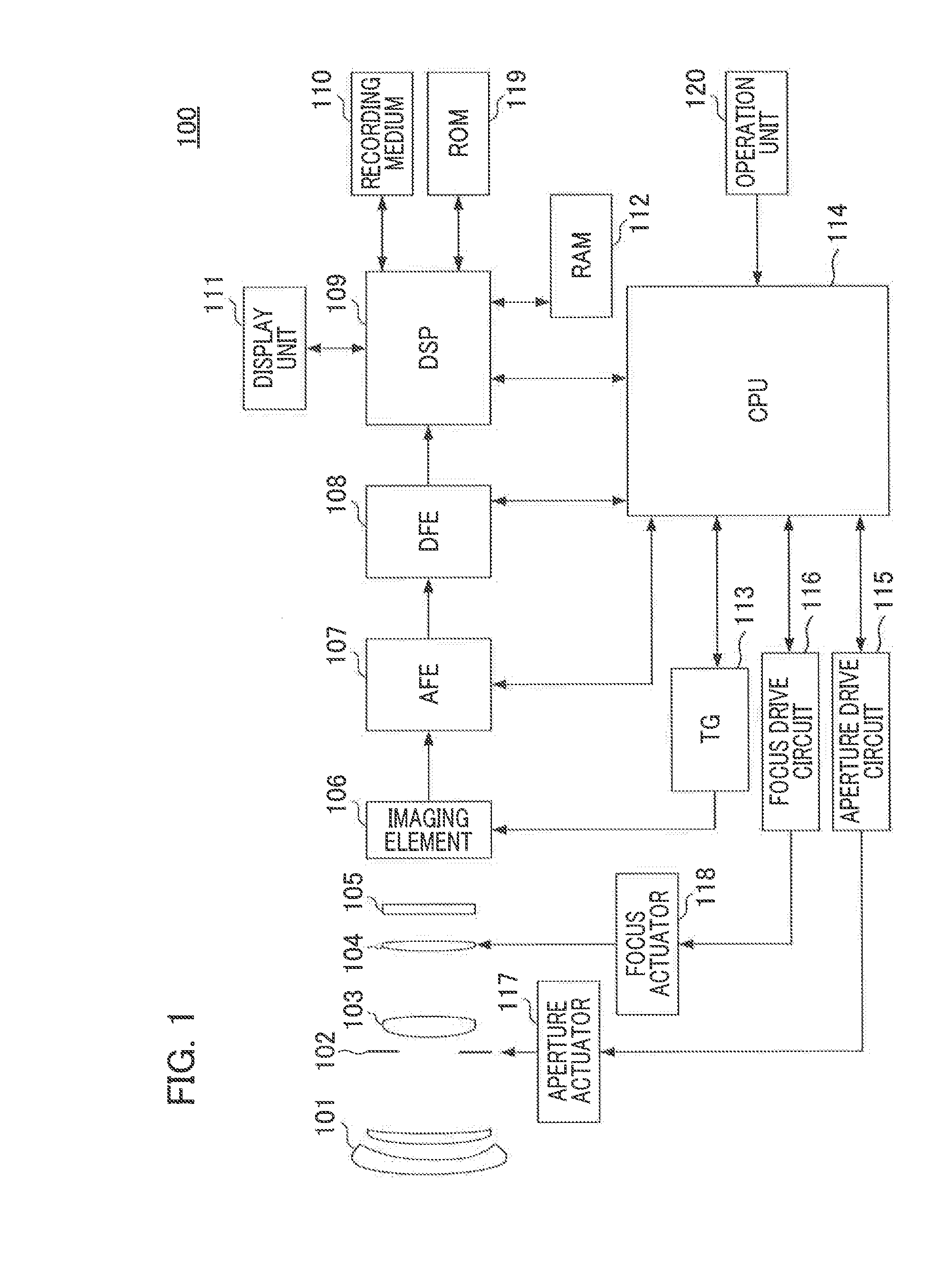
[0022]Hereinafter, preferred embodiments of the present invention will be described with reference to the drawings. FIG. 1 is a diagram illustrating an overall configuration of an imaging apparatus 100 according to an embodiment of the present invention.

[0023]A first lens group 101 is an imaging optical system arranged at the front end (object side) of a lens barrel, and is held so as to be extendable and retractable in the optical axis direction. An aperture 102 adjusts its aperture diameter to adjust the light quantity when shooting. A second lens group 103 has a variable power action (zooming function) in synchronism with the reciprocal movement of the first lens group 101. A third lens group 104 is a focus-adjusting lens (focus lens) for focusing by advancing and retracting in the optical axis direction. An optical low-pass filter 105 is an optical element for reducing the false color or moiré of a shot image.

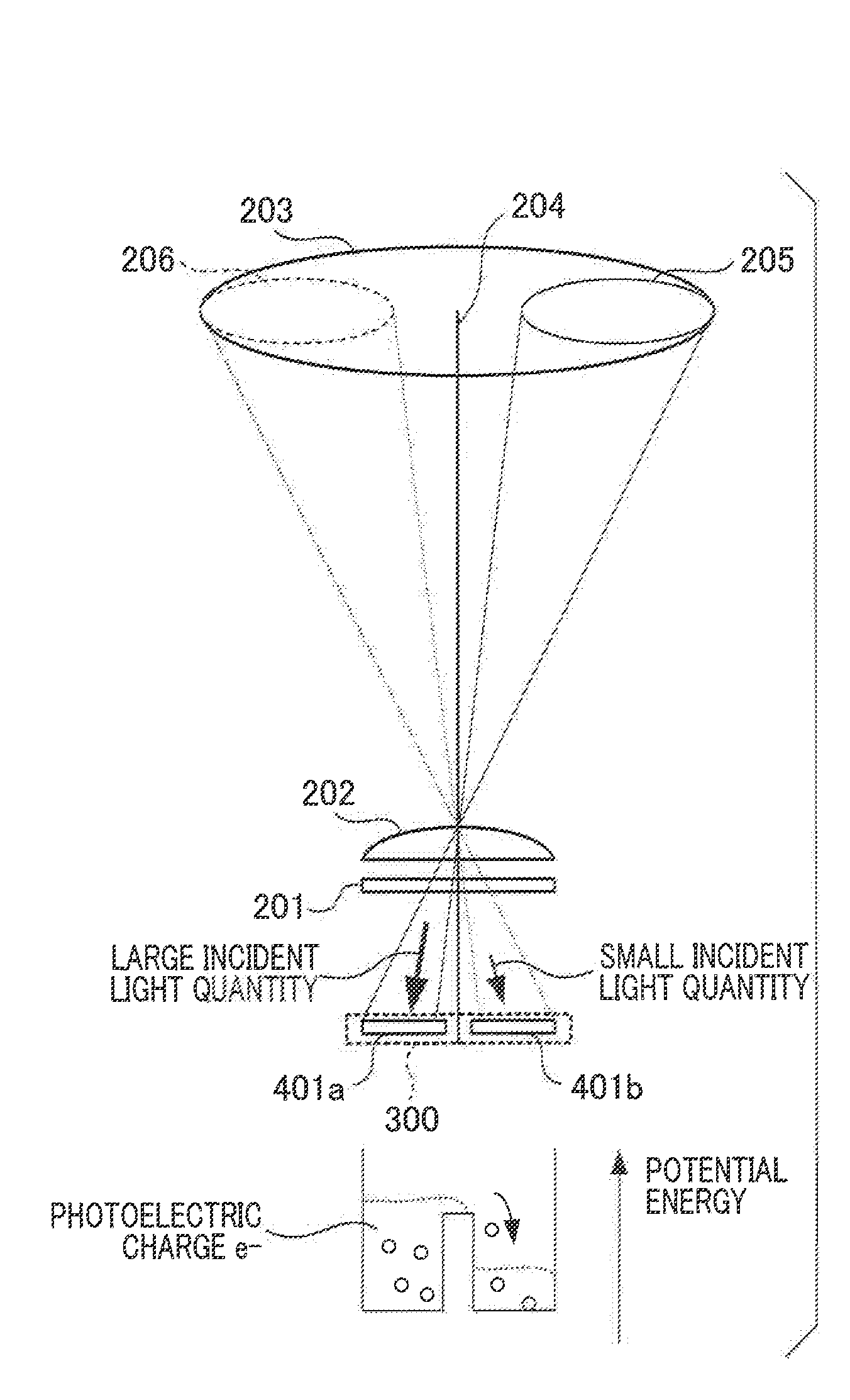
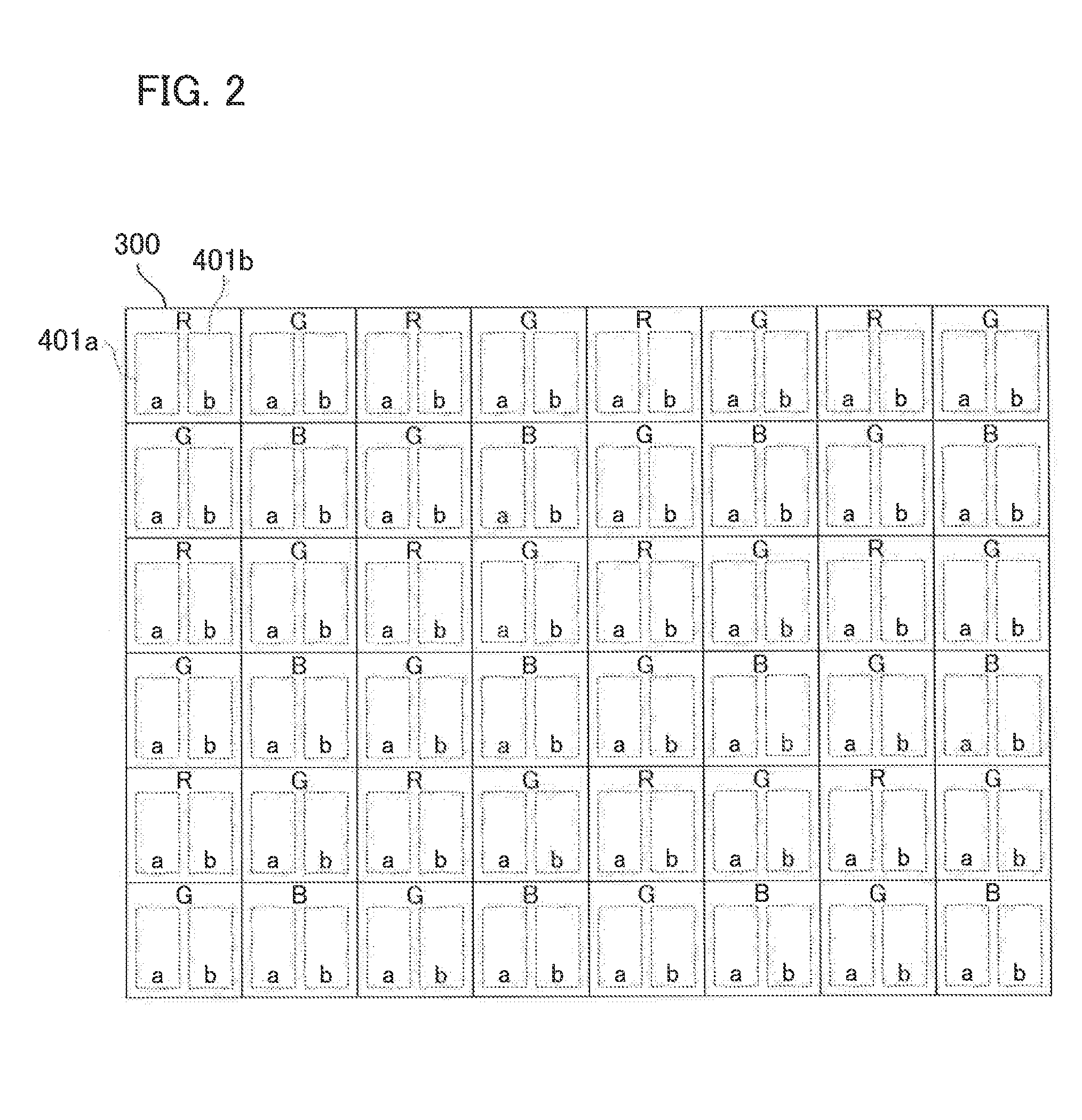
[0024]An imaging element 106 photoelectrically converts an object imag...


PUM


Abstract

An imaging element includes pixel portions each having a first sub-pixel and a second sub-pixel and outputs a phase difference detection-type focus detecting signal. An image signal A includes information for the first sub-pixel and an image signal AB includes information for the second sub-pixel. A level determining unit compares the image signal A with a threshold value SHA and compares the image signal AB with a threshold value SHAB. A correlation calculation processing unit performs correlation calculation for a signal excluding the image signal A having a level exceeding the threshold value SHA and the image signal AB having a level exceeding the threshold value SHAB so as to output the result of calculation to a CPU. The CPU calculates a focal shift amount in accordance with the result of calculation and performs a focus adjusting operation by drive-controlling a focus lens.

Description

BACKGROUND OF THE INVENTION[0001]1. Field of the Invention[0002]The present invention relates to an imaging apparatus using an imaging element having a plurality of photoelectric conversion units included in each pixel and a method for controlling the same.[0003]2. Description of the Related Art[0004]In recent years, multifunctioning for imaging apparatuses using an imaging element such as a CMOS (complementary metal-oxide film semiconductor) sensor or the like has been developed. Not only generation of still image data or moving image data but also control of an imaging apparatus such as focus adjustment are performed based on image information obtained by an imaging element.[0005]Japanese Patent Laid-Open No. 2001-124984 discloses a technique that performs pupil division focus detection using an imaging signal obtained from an imaging element. One microlens and two photodiodes are provided for each pixel of the imaging element, so that each photodiode receives light fluxes transmi...

Claims


Application Information

Patent Timeline
IPC IPC(8): H04N5/225G02B15/14
CPCG02B15/14H04N5/2254G02B7/34G02B15/143H04N23/672H04N23/72H04N25/704H04N25/134
Inventor UCHIDA, MINEO
Owner CANON KK
Learn More