Linear ultrasonic motor and optical apparatus including the same

a technology of ultrasonic motors and optical apparatuses, applied in piezoelectric/electrostrictive/magnetostrictive devices, mountings, instruments, etc., can solve the problems of frictional drive rails of ultrasonic vibrations of vibration bodies, increasing the thickness of motors, etc., and achieve the effect of reducing thickness

Active Publication Date: 2014-09-25
CANON KK
View PDF5 Cites 27 Cited by
  • Summary
  • Abstract
  • Description
  • Claims
  • Application Information

AI Technical Summary

Benefits of technology

[0007]The present invention has been made In view of such a problem, and has an object to achieve a compact linear ultrasonic motor with a reduced thickness in the pressurizing direction.

Problems solved by technology

As a result, ultrasonic vibrations of the vibration body frictionally drive the rail.
This arrangement causes a problem of increasing the thickness of a motor including a drive unit and a unit to be driven.

Method used


Image

  • Linear ultrasonic motor and optical apparatus including the same
  • Linear ultrasonic motor and optical apparatus including the same
  • Linear ultrasonic motor and optical apparatus including the same

Examples


embodiment 1

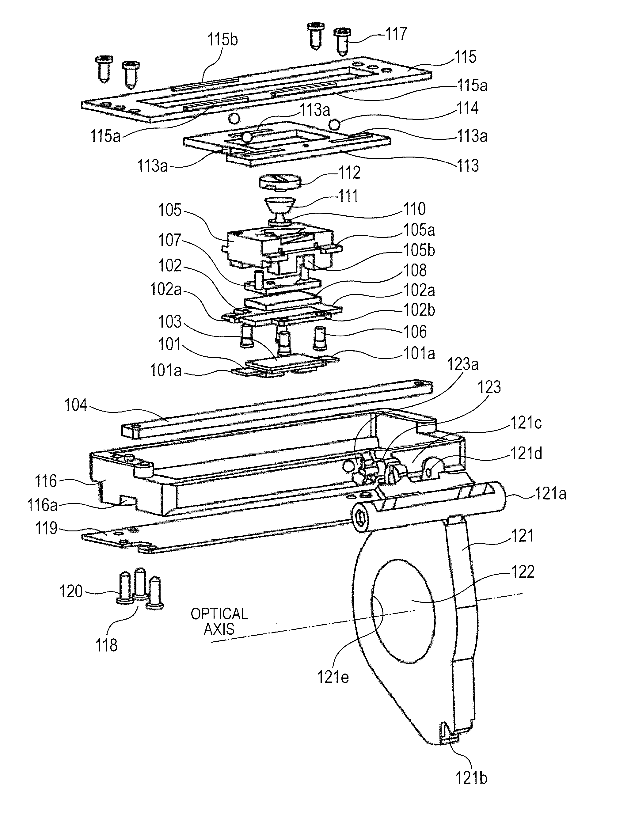
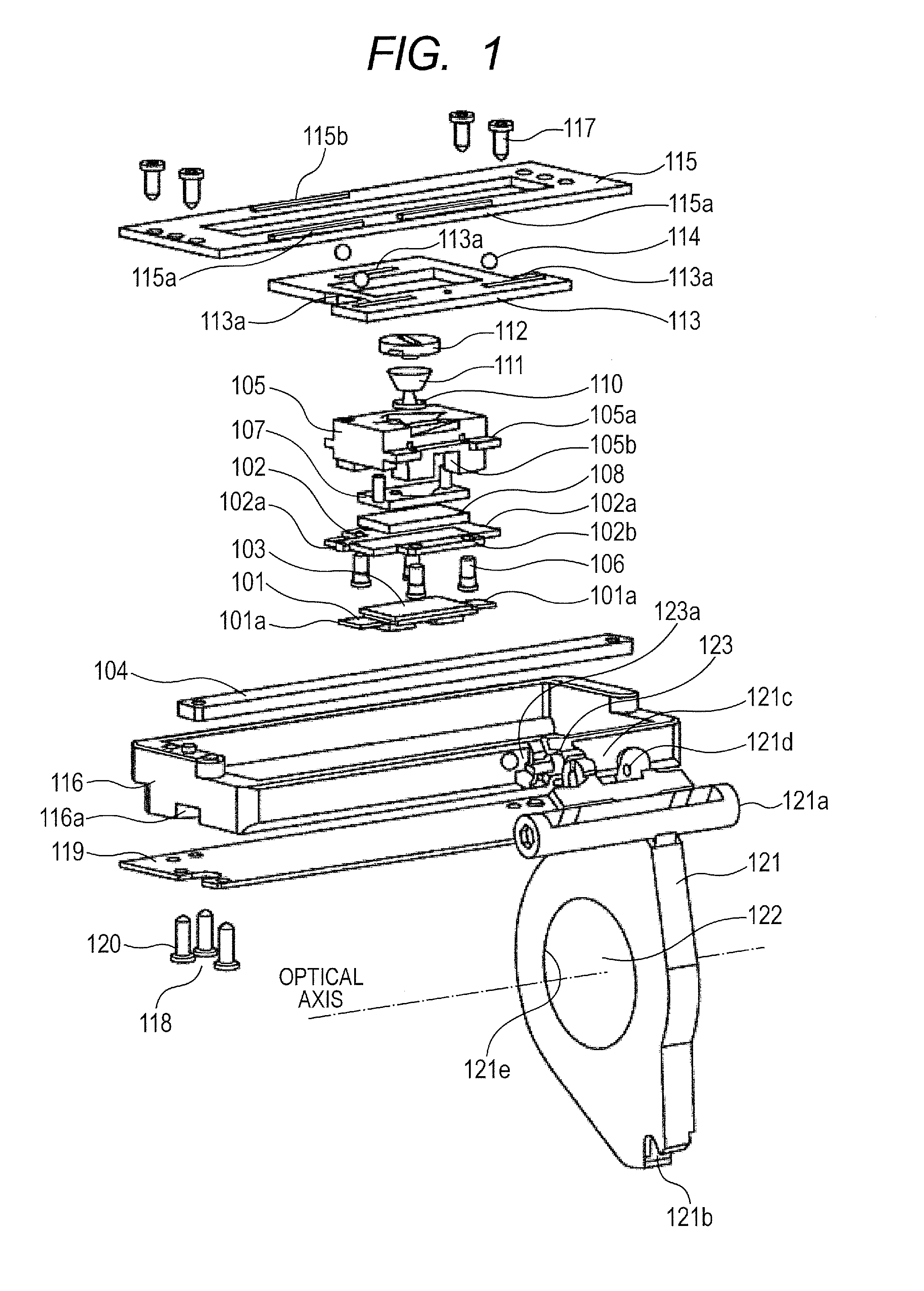
[0018]FIG. 1 is a principal perspective view illustrating a linear ultrasonic motor that is an embodiment of the present invention and used as a focus drive mechanism applied to a digital camera. A vibration plate 101 is fixed, at portions 101a to be in contact, to respective contact portions 102a of a connecting member 102 by welding. A vibration element includes the vibration plate 101, the connecting member 102 and a piezoelectric element 103.

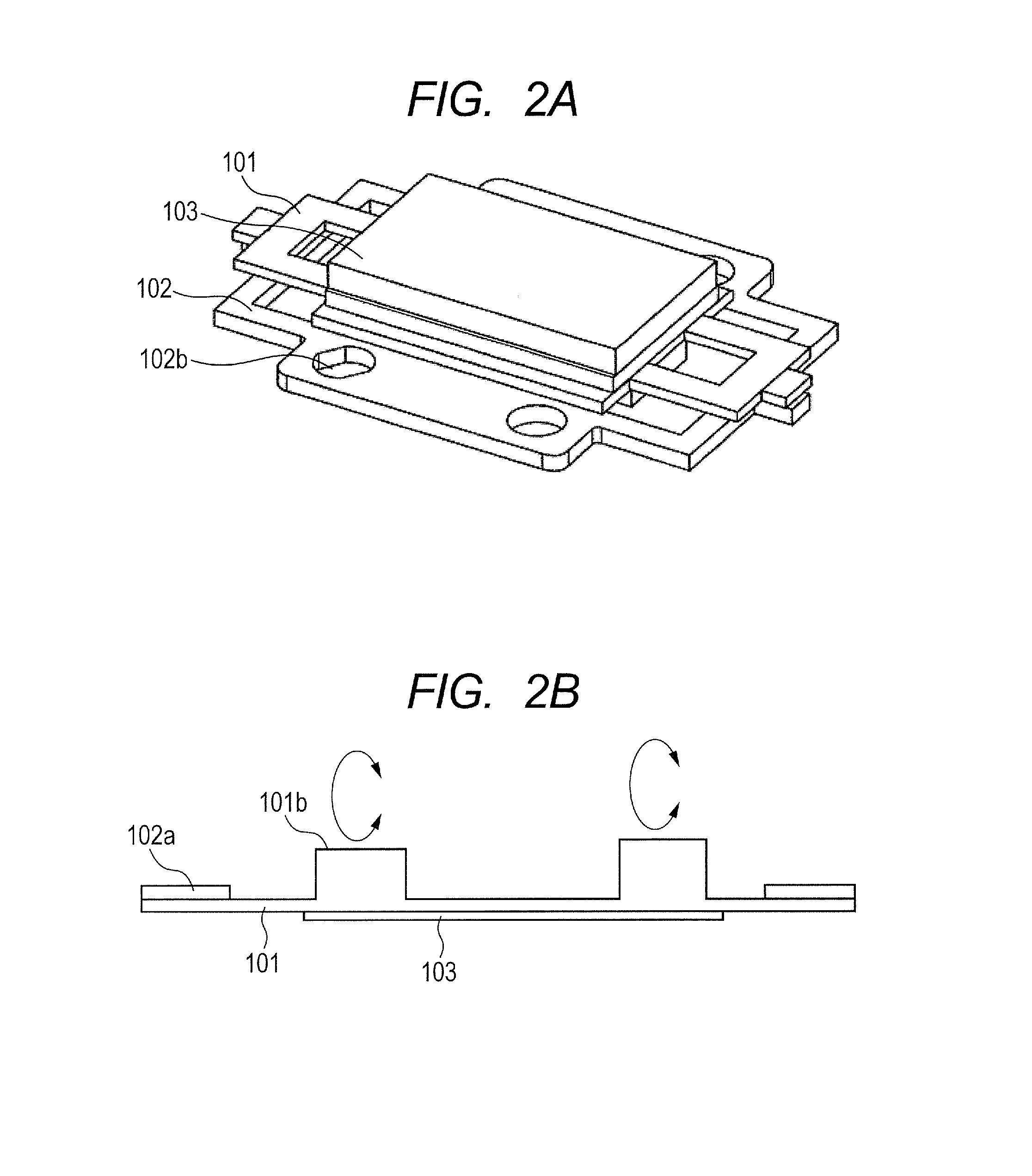
[0019]FIG. 2A is a principal perspective view illustrating the vibration element including the vibration plate 101, the connecting member 102 and the piezoelectric element 103. As illustrated in FIG. 2A, the piezoelectric element 103 is fixed to the vibration plate 101 with a publicly known adhesive. The piezoelectric element 103 is configured such that application of a high frequency voltage resonates the vibration plate 101 in the longitudinal direction, which is the X-axis direction, and the short direction, which is the Y-axis direction....


PUM


Abstract

A small linear ultrasonic motor includes: a vibration element generating ultrasonic vibrations by applying high frequency drive voltage; a slider against which vibration element is pressed and which is relatively moved by the ultrasonic vibrations; a vibration element supporting member retaining the vibration element and relatively moving with respect to the slider; a guide portion guiding a moving direction of the relative movement of the vibration element supporting member; and a pressurizing portion pressing the vibration element against the slider, wherein the guide portion is arranged sandwiching a position at which the vibration element is pressed against the slider, in a plane that includes the moving direction and intersects with a pressurizing direction of a pressurizing force exerted by the pressurizing portion, and at least each part of the pressurizing portion and the guide portion is disposed at a position equidistant from the plane in the pressurizing direction.

Description

BACKGROUND OF THE INVENTION[0001]1. Field of the Invention[0002]The present invention relates to an ultrasonic motor, in particular to a linear drive ultrasonic motor and to an optical apparatus including the same.[0003]2. Description of the Related Art[0004]A technique has been known where, in a conventional linear drive ultrasonic motor (hereinafter, called a linear ultrasonic motor), a piezoelectric element for generating periodical vibrations in an ultrasonic range by applying a high frequency voltage is adopted as a vibration element, and a slide member pressed thereagainst is driven by the vibrations.[0005]For instance, as a linear ultrasonic motor, a configuration disclosed in Japanese Patent Application Laid-Open No. 2001-292584 is exemplified. This configuration has a function of supporting a vibration node portion of a vibration body (a vibration element in the present invention), and a function of pressurizing the vibration body to cause a frictional force between the vib...

Claims


Application Information

Patent Timeline
Patent Type & Authority Applications(United States)
IPC IPC(8): H02N2/02
CPCH02N2/026G02B7/102H02N2/006
Inventor YAMAMOTO, HARUSHIGE
Owner CANON KK
Why Eureka
Try Eureka