Method and System for Checking the Color Quality of Preforms

a color quality and preform technology, applied in the direction of optical radiation measurement, instruments, spectrometry/spectrophotometry/monochromators, etc., can solve the problems of high cost, high manufacturing process, and high manufacturing process cost, and achieve optimal image evaluation, good picture quality, and better image evaluation

Active Publication Date: 2014-09-25
FINATEC HLDG
View PDF8 Cites 8 Cited by
  • Summary
  • Abstract
  • Description
  • Claims
  • Application Information

AI Technical Summary

Benefits of technology

[0018]In still another embodiment of the present invention, pluralities of images are evaluated in order to determine a flawless series of preforms. The advantage of this embodiment is that a statistically relevant number of pictures may be taken before a defect is determined. A certain tolerance in the evaluation can thereby be taken into account.
[0019]In another embodiment of this invention, the preforms are illuminated by means of at least one lighting fixture when making the image. The advantage of this embodiment is above all that when taking the pictures of the preforms to be checked a sufficient illumination of the preforms may be ensured. A good picture quality can thereby be guaranteed, which leads to a better evaluation of the images.
[0020]Preferably the at least one lighting fixture is positioned behind the projection screen or respectively the plate so that the preforms are illuminated from behind with respect to the imaging direction. Thanks to an illumination from behind (in relation to the direction of view of the imaging device) the preforms can be well illuminated, whereby the various deficiencies may also be detected much more easily and much more precisely. To this end the lighting fixture can be disposed advantageously behind the transparent region of the projection screen or respectively plate.
[0021]In another embodiment of the present invention, preforms slide over the plate, after leaving the transport device, in such a way that they are led into the collection vessel. Thanks to this plate the preforms can be channeled, on the one hand, and, on the other hand, they can be brought into one plane, it being possible for them to continue to be unordered in this plane. They can e.g. be e.g. at different spacings or in different alignment. This embodiment of the present invention has inter alia the advantage that the preforms are positioned optimally with respect to the imaging device, without special alignment devices having to be used. The preforms are aligned at a defined spacing to the imaging device. Moreover this plate also serves as the background in the pictures, as described above, so that an optimal evaluation of the image is made possible.
[0022]In another variant of the present invention the plate is perforated and is designed, for example, as a perforated plate. The use of such a plate has the advantage that the weight of the plate and of the entire facility can be reduced without the functionality of the plate becoming lost.
[0023]In a further variant of the present invention at least a portion of the plate is curved at least in one direction. For example, the curvature can extend transversely to the direction of the sliding of the preforms. Preferably it is possible for the plate to be curved in such a way that at least one channel is formed for the sliding preforms. In this way the sliding characteristics of the preforms may be better influenced, and it can be ensured that all preforms slide over a certain region of the plate. It is thereby possible to configure the taking of the picture of the sliding preforms more precisely since the distribution of the preforms in front of the imaging device can be limited in a further dimension. Thus with a channel-shaped plate the sliding preforms can be partially ordered so that the evaluation of the images can be made in a simpler and faster way.

Problems solved by technology

Because manufacturing processes are energy-intensive and because, as a rule, the manufacturing processes have to be stopped upon discovery of preforms that are not flawless (incurring higher costs), manufactured preforms as well as other mentioned preform-like articles are checked as a rule before they are sent to further processing.
Possible defects in the manufactured preforms are above all imprecise dimensions, irregular shape, too thin or too thick wall areas, pin holes, burns, presence of foreign bodies and / or bubbles, but also deficient color quality.
However this means that the examination of the objects to be checked cannot be carried out already in the manufacturing machine, but instead a separate checking system is always necessary downstream from the manufacturing machine.
This once again means that the installation and the interface between the two systems are complex, and that they are only able to be achieved using qualified personnel.
Moreover such checking systems require additional space, which is not always available with existing manufacturing machines.

Method used


Image

  • Method and System for Checking the Color Quality of Preforms
  • Method and System for Checking the Color Quality of Preforms
  • Method and System for Checking the Color Quality of Preforms

Examples


first embodiment

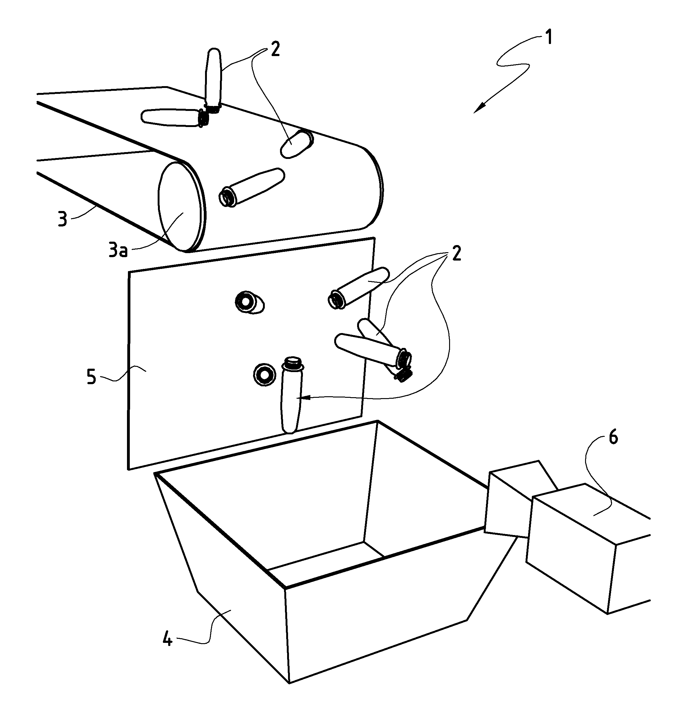
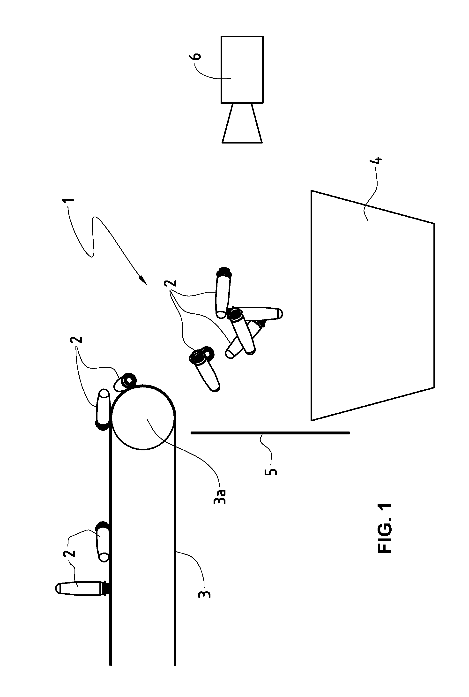
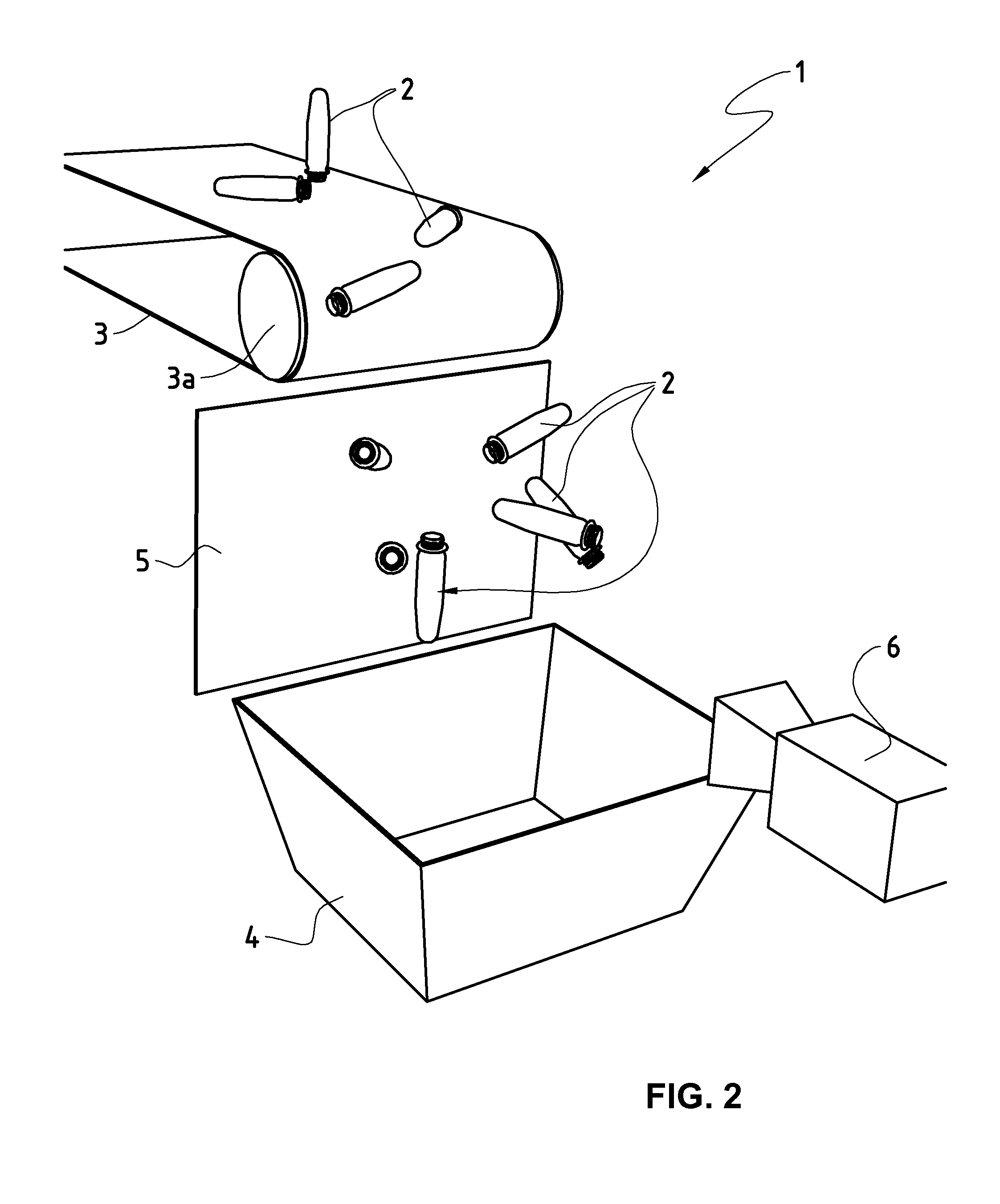
[0036]Illustrated in FIG. 1 and FIG. 2 is schematically a system 1 for checking the color quality of preforms according to one embodiment of the present invention.

[0037]The preforms 2 produced in a conventional manufacturing machine or respectively in a conventional manufacturing system of plastic (e.g. PET) are transported unordered by the transport device 3 to a collection vessel 4. Understood by the term unordered should be an arrangement of preforms that results “naturally”, i.e. without a previous ordering or respectively sorting. Of course it is also conceivable that the preforms 2 are passed on by the transport device not to a collection vessel 4, but to a further transport device. However the present invention also works the same way also in this alternative case. The transport device 3 in FIGS. 1 and 2 is a conventional conveyor belt with a drive roller 3a, which is driven via a drive (not shown). It is however conceivable of course to use another suitable transport device,...

second embodiment

[0045]One image is illustrated schematically in FIGS. 5a and 5b made with the system according to the first or respectively second embodiment of the invention. Images of a plurality of preforms may be identified in this picture. The projection screen can be seen in FIG. 5a, and the plate 5′ in FIG. 5b, in the background of the picture. In FIGS. 5a and 5b the images of preforms bear the reference number 7 (instead of 2) so that they are able to be distinguished from the “genuine” preforms. In other words, the preforms designated by 7 represent preforms that are representative for all preforms. The preforms 7 are in an area in front of the projection screen 5 that is suitable for obtaining images suitable for evaluation using the processing device. The area is defined e.g. by a spacing to the imaging system 6.

[0046]In the image, given by way of example, according to FIG. 5a it can be seen that the preforms 7 are unordered. In this sense the image of certain preforms 7 is incomplete un...


PUM

PropertyMeasurementUnit
color qualityaaaaaaaaaa
coloraaaaaaaaaa
transparentaaaaaaaaaa

Abstract

The present invention relates to a method and the corresponding system for checking the color quality of preforms (2) intended for the manufacture of containers, in particular beverage bottles, the preforms (2) being transported to a collection vessel (4) by a transport device (3), and an image of the preforms (2) being made by means of an imaging device (6) and being transmitted to a processing device for checking, in which the preforms (2) are led unsorted into the collection vessel (4) upon leaving the transport device (3), the image being made between the leaving of the transport device (3) and the collection vessel (4), and in which the image is processed by the processing device in such a way that the color quality of the preforms (2) and/or defective preforms (2) are discovered.

Description

TECHNICAL FIELD OF THE INVENTION[0001]The present invention relates to a method and a corresponding system for checking the color quality of preforms intended for the manufacture of containers, in particular beverage bottles. In particular the present invention relates to a method and a corresponding system for checking the color quality of preforms, in which the preforms are transported by a transport device into a collection vessel by a transport device, and an image being made of the preforms by means of an imaging device and being transmitted to a processing device for checking.[0002]It should be mentioned here that the term “preform”, used in the following, is not to be understood in a limiting way. In particular this term covers all pieces used for the manufacture of containers, for instance beverage bottles, but also all similar objects the production methods for which or respectively the structure and / or appearance of which are similar to the conventional preforms. Examples ...

Claims


Application Information

Patent Timeline
Patent Type & Authority Applications(United States)
IPC IPC(8): G01J3/50
CPCB29K2105/258G01J3/50B29K2105/253G01N21/9081B29C45/7686
Inventor HERMLE, MATTHIASMAIBACH, FRIDOLINSCHLUP, BEAT
Owner FINATEC HLDG
Why Eureka
Try Eureka