Tin-plated copper-alloy material for terminal having excellent insertion/extraction performance

a technology of tin-plated copper alloy and terminal, which is applied in the direction of metal/alloy conductors, conductors, and transportation and packaging, etc., can solve the problems of deteriorating productivity, inability to reduce a dynamic friction coefficient to 0.3 or less, and deteriorating productivity, etc., to achieve excellent soldering wettability, reduce dynamic friction coefficient, and reduce contact resistance

Inactive Publication Date: 2014-09-25
MITSUBISHI MATERIALS CORP
View PDF1 Cites 10 Cited by
  • Summary
  • Abstract
  • Description
  • Claims
  • Application Information

AI Technical Summary

Benefits of technology

[0022]According to the present invention, since the dynamic friction coefficient is reduced, the low contact resistance, the excellent soldering wettability and the low insertion / extraction performance can be realized. Moreover, since the dynamic friction coefficient is small even with the low load, it is suitable for small terminals. Particularly, it is advantageous in terminals used for automobiles or electronic elements, at parts in which the low insertion force for connecting, the suitable contact resistance, and the excellent soldering wettability are necessitated.

Problems solved by technology

When the connector have a lot of pins, even though a force for inserting the connector for a pin is s all, a large force is required for inserting the connector for all pins; therefore, it is apprehended that productivity is deteriorated.
However, it is not possible to reduce a dynamic friction coefficient to 0.3 or less.
Productivity may be deteriorated by an increase of insertion force for inserting a connector as the connector is miniaturized and the pins of the connector is increased.
It is effective to reduce P in order to reduce F. However, in order to maintain electrical connection reliability between the male and female terminals when the connectors are fitted, it is not possible to reduce the contact pressure aimlessly.

Method used


Image

  • Tin-plated copper-alloy material for terminal having excellent insertion/extraction performance
  • Tin-plated copper-alloy material for terminal having excellent insertion/extraction performance
  • Tin-plated copper-alloy material for terminal having excellent insertion/extraction performance

Examples


examples

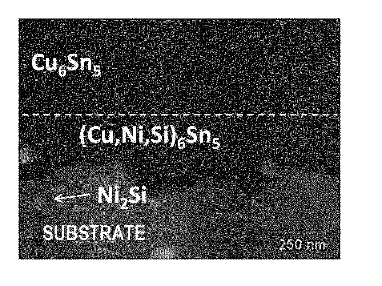
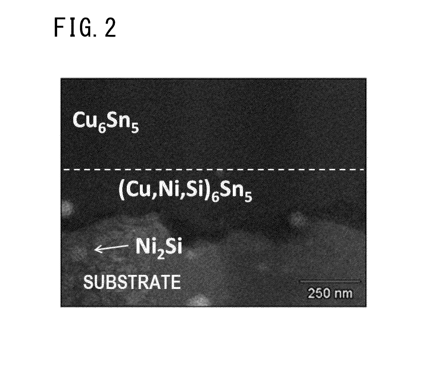
[0042]The substrate was a plate of copper alloy (Ni; 0.5% or more and 5.0% or less by mass-Zn; 1.0%-Sn; 0% or more and 0.5% or less by mass-Si; 0.1% or more and 1.5% or less by mass-Fe; 0% or more and 0.03% or less by mass-Mg; 0.005% by mass) having a plate thickness of 0.25 mm, after polishing and roughening of the surface of the substrate, and Cu-plating and Sn-plating were performed in sequence. In this case, plating conditions of the Cu-plating and the Sn-plating were as shown in Table 1. In Table 1, Dk is an abbreviation for current density for a cathode; and ASD is an abbreviation for A / dm2.

TABLE 1Cu PLATINGSn PLATINGCOMPOSITIONCOPPER250 g / LTIN75 g / LOF PLATINGSULFATESULFATESOLUTIONSULFURIC 50 g / LSULFURIC85 g / LACIDACIDADDITIVE10 g / LSOLUTION25° C.20° C.TEMPERATUREDk5 ASD5 ASD

[0043]After plating at the thickness shown in Table 2, in Examples and Comparative Examples, the surface temperature of the substrates were held in the reduction atmosphere as reflow treatments in which the ...


PUM

PropertyMeasurementUnit
arithmetic average roughnessaaaaaaaaaa
oil-sump depth Rvkaaaaaaaaaa

Abstract

Tin-plated copper-alloy terminal material in which Sn-based surface layer is formed on a surface of a substrate made of Cu alloy, and a Cu—Sn alloy layer is formed between the Sn-based surface layer and the substrate; the Cu—Sn alloy layer contains Cu6Sn5 as major proportion and has a compound in which a part of Cu in the Cu6Sn5 is substituted by Ni and Si in the vicinity of a boundary face at the substrate side; an arithmetic average roughness Ra of the Cu—Sn alloy layer is 0.3 μm or more in at least one direction and an arithmetic average roughness Ra in all direction is 1.0 μm or less; an oil-sump depth Rvk of the Cu—Sn alloy layer is 0.5 μm or more; and an average thickness of the Sn-based surface layer is 0.4 μm or more and 1.0 μm or less and dynamic friction coefficient is 0.3 or less.

Description

BACKGROUND OF THE INVENTION[0001]1. Field of the Invention[0002]The present invention relates to tin-plated copper-alloy material for terminal that is useful for a terminal for a connector used for connecting electrical wiring of automobiles or personal products, in particular, which is useful for a terminal for a multi-pin connector.[0003]Priority is claimed on Japanese Patent Application No. 2013-62324, filed on Mar. 25, 2013 and Japanese Patent Application No. 2013-248189, filed on Nov. 29, 2013, the content of which is incorporated herein by reference.[0004]2. Background Art[0005]Tin-plated copper-alloy material for terminal is formed by reflowing after Cu-plating and Sn-plating on a substrate made of copper alloy so as to have a Sn-based surface layer as a surface layer and a Cu—Sn alloy layer as a lower layer, and is widely used as material for terminal.[0006]In recent years, for example, electrification is rapidly progressed in vehicle and circuits are increased in the electr...

Claims


Application Information

Patent Timeline
Patent Type & Authority Applications(United States)
IPC IPC(8): H01B1/02
CPCH01B1/026C25D3/30C25D3/38C25D5/10C25D5/34C25D5/505Y10T428/12715H01R13/03
Inventor KATO, NAOKIINOUE, YUKITARUTANI, YOSHIE
Owner MITSUBISHI MATERIALS CORP
Why Eureka
Try Eureka