
Catalysts for low temperature electrolytic co2 reduction

a technology of electrolysis and catalysts, applied in the field of co2 reduction, can solve the problems of 750-900° c, inability to access other products, and none that is efficient and stable enough for practical use, and achieve the effect of reducing co2

Active Publication Date: 2014-10-02
THE BOARD OF TRUSTEES OF THE LELAND STANFORD JUNIOR UNIV
View PDF2 Cites 31 Cited by
  • Summary
  • Abstract
  • Description
  • Claims
  • Application Information

AI Technical Summary

Benefits of technology

The patent describes a method and apparatus for electrochemically reducing CO2. The method involves using a cathode with a metal and a metal oxide coating, which is exposed to CO2 and H2O, while the anode is exposed to H2O. A voltage is applied between the cathode and anode, resulting in the reduction of CO2 to CO. The apparatus includes an anode, an oxidized cathode, a chamber for exposing the anode and oxidized cathode to at least one electrolyte, and a gas chamber for exposing the oxidized cathode to CO2. The invention provides an efficient method for reducing CO2 using electrochemical means.

Problems solved by technology

Solid oxide electrolytic cells reduce CO2 to CO efficiently at high current densities, but require operating temperatures of 750-900° C. and cannot access other products.
Researchers over the past three decades have identified several materials that are capable of reducing CO2 electrochemically in aqueous solutions, but none that is efficient and stable enough for practical use.
In general, available electrodes suffer from one or more of three major problems: 1) a requirement for excessive reducing potentials (“overpotentials”) to reduce CO2 in preference to reducing H2O, resulting in low energetic efficiency; 2) rapid loss of CO2 reduction activity resulting from electrode poisoning; 3) production of multiple CO2 reduction products with little selectivity.

Method used


Image

  • Catalysts for low temperature electrolytic co2 reduction
  • Catalysts for low temperature electrolytic co2 reduction
  • Catalysts for low temperature electrolytic co2 reduction

Examples


embodiments of implementation

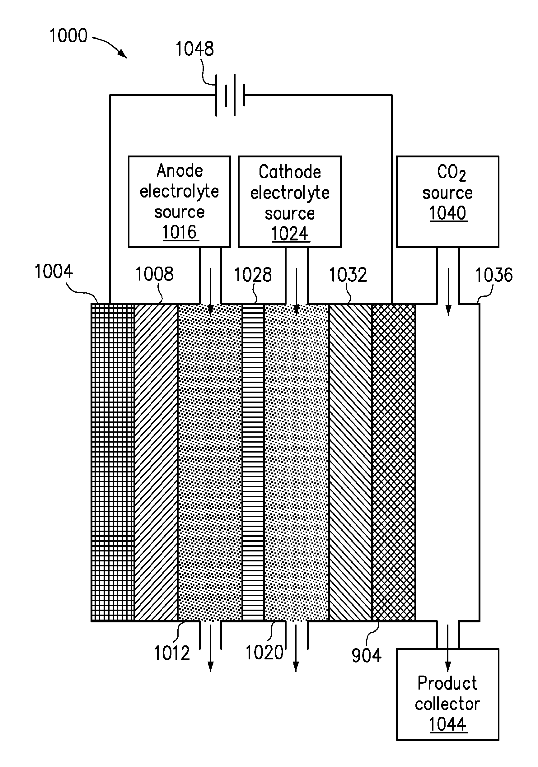
[0054]To facilitate understanding of the invention, FIG. 8 is a high level flow chart of an embodiment of the invention. In this embodiment, a cathode with a catalyst metal is provided (step 804). A metal oxide coating is formed on the catalyst metal (step 808). The metal oxide coating and the catalyst metal form a metal and metal oxide coating, which may comprise a metal oxide coating over a metal coating or a single coating with both metal oxide particles and metal particles. An anode is spaced apart from the cathode (step 812). An ionic transport is provided between the anode and cathode (step 816). The cathode is exposed to CO2 and H2O (step 820). The anode is exposed to H2O (step 824). A voltage is provided between the cathode and anode (step 828). The voltage causes CO2 and H2O to be reduced to CO, H2, and O2. The CO and H2 may be converted to hydrocarbon or alcohol products.

[0055]In a specific embodiment of the invention, the cathode is formed by providing a conductive substr...


PUM

PropertyMeasurementUnit
Temperatureaaaaaaaaaa
Thicknessaaaaaaaaaa

Abstract

A method for electrochemically reducing CO2 is provided. A cathode is provided, wherein the cathode comprises a conductive substrate with a catalyst of a metal and a metal oxide based coating on a side of the cathode. An anode is spaced apart from the cathode. An ionic transport is provided between the anode and cathode. The cathode is exposed to CO2 and H2O. The anode is exposed to H2O. A voltage is provided between the cathode and anode.

Description

CROSS REFERENCE TO RELATED APPLICATIONS[0001]This application claims priority under 35 U.S.C. §119 from U.S. Provisional Patent Application No. 61 / 511,824, filed Jul. 26, 2011, entitled CERIA-BASED ELECTROREDUCTION CATALYSTS FOR LOW-TEMPERATURE ELECTROLYTIC SYNGAS PRODUCTION and U.S. Provisional Patent Application No. 61 / 579,422, filed Dec. 22, 2011, entitled CATALYSTS FOR LOW TEMPERATURE ELECTROLYTIC CO2 REDUCTION, which are incorporated herein by reference for all purposes.BACKGROUND OF THE INVENTION[0002]This invention relates generally to the reduction of CO2. Sustainable production of C-based fuel requires using renewable energy to power the reductive fixation of CO2. Coupling renewable electricity to an electrolytic device is an attractive strategy for this goal because it enables the use of multiple renewable energy sources and independent optimization of catalysis. Solid oxide electrolytic cells reduce CO2 to CO efficiently at high current densities, but require operating te...

Claims


Application Information

Patent Timeline
IPC IPC(8): C25B11/04C25B1/00C25B3/25
CPCC25B1/00C25B11/0478C25B3/25C25B11/091
Inventor KANAN, MATTHEW W.CHEN, YIHONGLI, CHRISTINA
Owner THE BOARD OF TRUSTEES OF THE LELAND STANFORD JUNIOR UNIV
Learn More