Phosphor device and illumination system using same

a technology of phosphor powder and illumination system, which is applied in the direction of fixed installation, lighting and heating apparatus, instruments, etc., can solve the problems of not being able to achieve the theoretical value of the conventional powder-mixing method of prior art, not knowing the exact composition of each phosphor powder, and relatively difficult to mix the phosphor powders for obtaining the target phosphor agent, etc., to achieve the effect of reducing the difficulty of fabricating phosphor powders, low color saturation ratio ratio

Active Publication Date: 2014-10-02
DELTA ELECTRONICS INC
View PDF2 Cites 4 Cited by
  • Summary
  • Abstract
  • Description
  • Claims
  • Application Information

AI Technical Summary

Benefits of technology

[0008]One embodiment of the present invention provides a phosphor device and an illumination system using the same in order to eliminate the drawbacks of the high fabricating difficulty of mixing phosphor powders and the low output efficiency, low color saturation and the color shift phenomena caused by the cascade effect.

Problems solved by technology

Nevertheless, different kinds of the phosphor powders may be fabricated by different companies, so it is not easy to know the exact composition of each phosphor powder.
Under this circumstance, it is relatively difficult to mix the phosphor powders for obtaining the target phosphor agent.
As a result, not only the theoretical value cannot be achieved by the conventional powder-mixing method of prior art, but also the color saturation and hue cannot be matched with the industry standard value, such as the standard value of Rec. 709 (or called ITU-R Recommendation BT.

Method used


Image

  • Phosphor device and illumination system using same
  • Phosphor device and illumination system using same
  • Phosphor device and illumination system using same

Examples


Embodiment Construction

[0023]The present invention will now be described more specifically with reference to the following embodiments. It is to be noted that the following descriptions of preferred embodiments of this invention are presented herein for purpose of illustration and description only. It is not intended to be exhaustive or to be limited to the precise form disclosed.

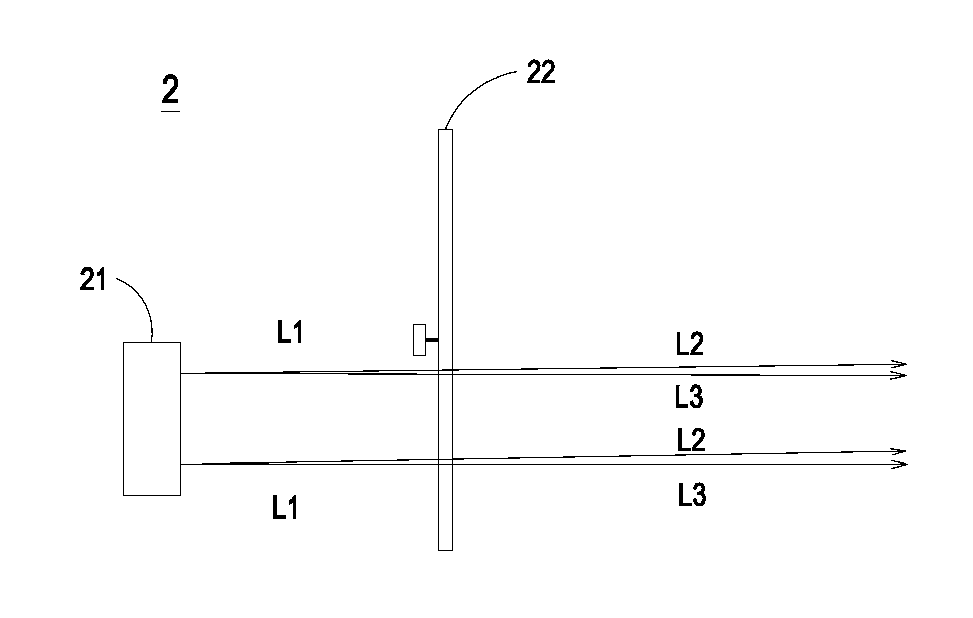
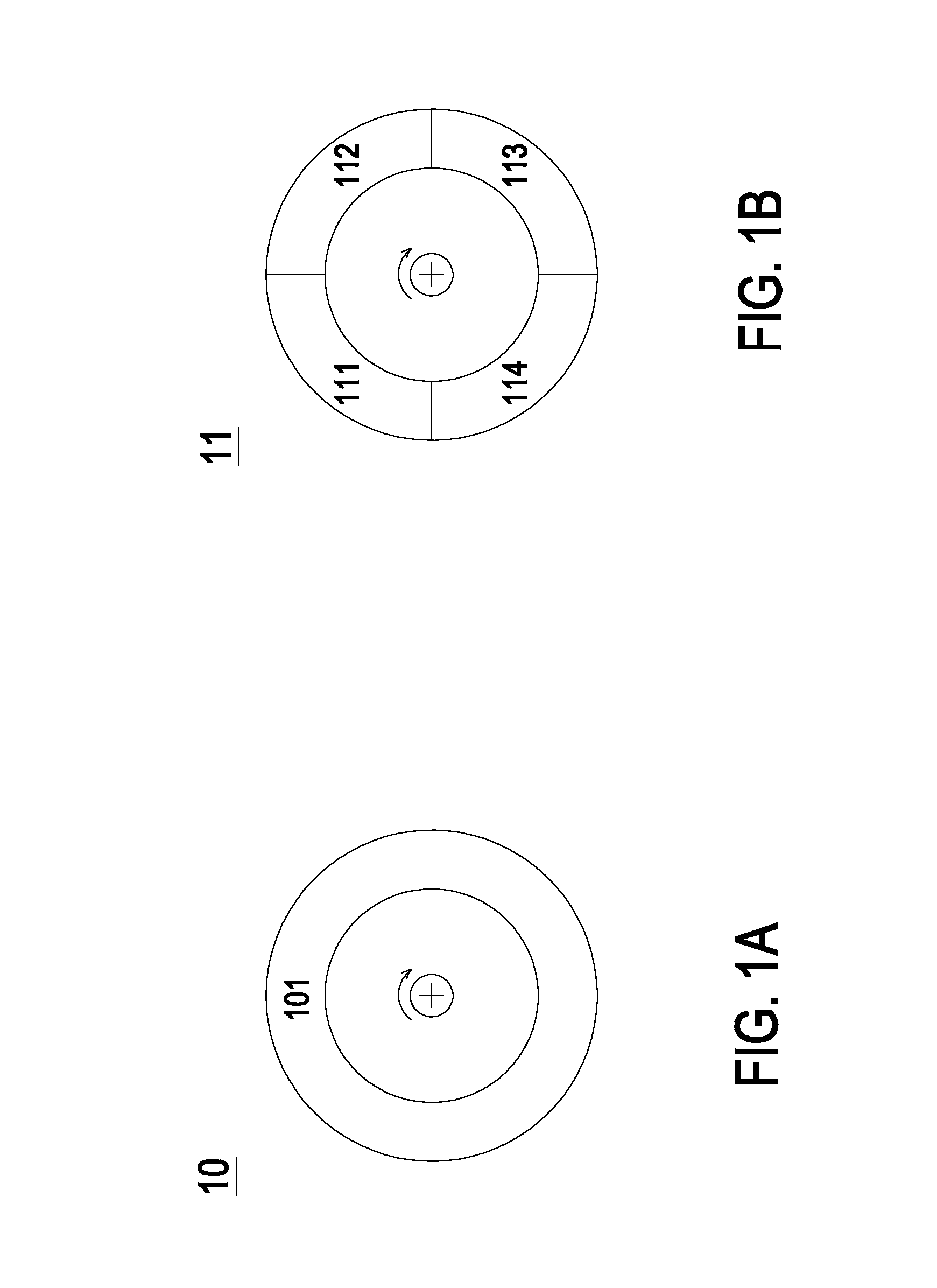
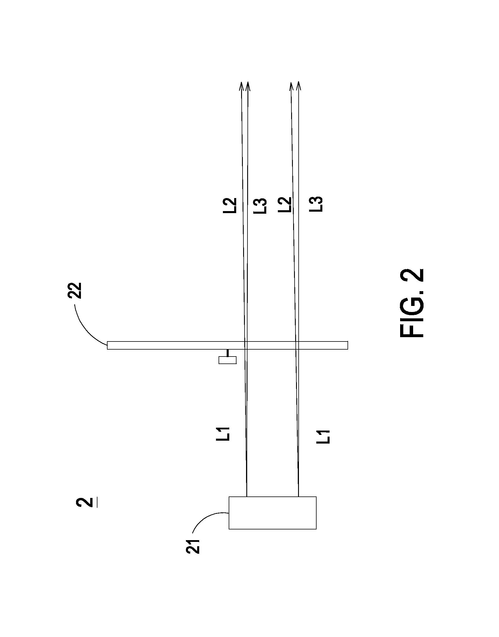
[0024]Please refer to FIG. 2, FIG. 3A and FIG. 3B. FIG. 2 schematically illustrates the configuration of an illumination system according to an embodiment of the present invention. FIG. 3A schematically illustrates the structure of a phosphor device according to an embodiment of the present invention. FIG. 3B schematically illustrates the structure of a phosphor device according to another embodiment of the present invention. As shown in FIG. 2, FIG. 3A and FIG. 3B, the illumination system 2 of one embodiment of the present invention is applied to projection apparatus like laser projectors, 3D-image projectors and real object pro...


PUM


Abstract

A phosphor device of an illumination system emitting a first color light in a first waveband region includes a first region having n sub-regions and n single-powder phosphor agents, wherein n is ≧2. The n single-powder phosphor agents are coated on the n sub-regions, respectively, for transforming the first color light in the first waveband region into n color lights in n waveband regions. The n sub-regions are arranged in a specific area ratio. The first color light in the first waveband region is cyclically transformed into a second color light in a second waveband region, a third color light in a third waveband region, . . . , and a (n+1)th color light in a (n+1)th waveband region in a specific time ratio according to the specific area ratio, such that the n color lights sequentially outputted in the specific time ratio are integrated as a specific color light.

Description

FIELD OF THE INVENTION[0001]The present invention relates to a phosphor device, and more particularly to a phosphor device with plural sub-regions for increasing the output efficiency and the light color diversity and an illumination system using the same.BACKGROUND OF THE INVENTION[0002]In recent years, lot types of projection device such as projectors are widely used in families, schools and business occasions in order to amplify and display an image signal provided by an image source on a screen. For the purpose of reducing the power consumption and the product size, a solid-state light-emitting element (e.g. a LED or a laser element) is employed in the illumination system of current projector to replace the conventional high intensity discharge (HID) lamp.[0003]In general, the illumination system of the projector should emit three primary color lights, i.e. red light (R), green light (G) and blue light (B). As for the luminous efficiency of the solid-state light-emitting element...

Claims


Application Information

Patent Timeline
Patent Type & Authority Applications(United States)
IPC IPC(8): F21K99/00
CPCF21K9/56G03B21/204G03B33/08G09G3/002
Inventor CHOU, YEN-ICHEN, CHI
Owner DELTA ELECTRONICS INC
Why Eureka
Try Eureka