Biochip

a biochip and chip technology, applied in the field of biochips, can solve the problems of excessive reaction time and achieve the effect of improving sensitivity

Active Publication Date: 2014-10-02
BOEHRINGER LNGELHEIM VETMEDICA GMBH
View PDF5 Cites 0 Cited by
  • Summary
  • Abstract
  • Description
  • Claims
  • Application Information

AI Technical Summary

Benefits of technology

The patent relates to a cost-effective and sensitive DNA chip that can be produced using impedance-spectroscopy. The chip has a larger number of catcher molecules arranged in its reaction layer, leading to improved sensitivity and better impedance-spectroscopic detection. The chip is also adapted to the space pervaded by the electric field, resulting in a more uniform distribution of catcher molecules and enhanced sensitivity. In summary, the patent provides a more effective and efficient tool for DNA analysis.

Problems solved by technology

In practice, however, the thickness of the reaction layer must not be chosen to be too large because this would result in excessively long diffusion paths and, associated therewith, excessively long reaction times for the transport of the target molecules to the catcher molecules.

Method used


Image

  • Biochip
  • Biochip
  • Biochip

Examples


Embodiment Construction

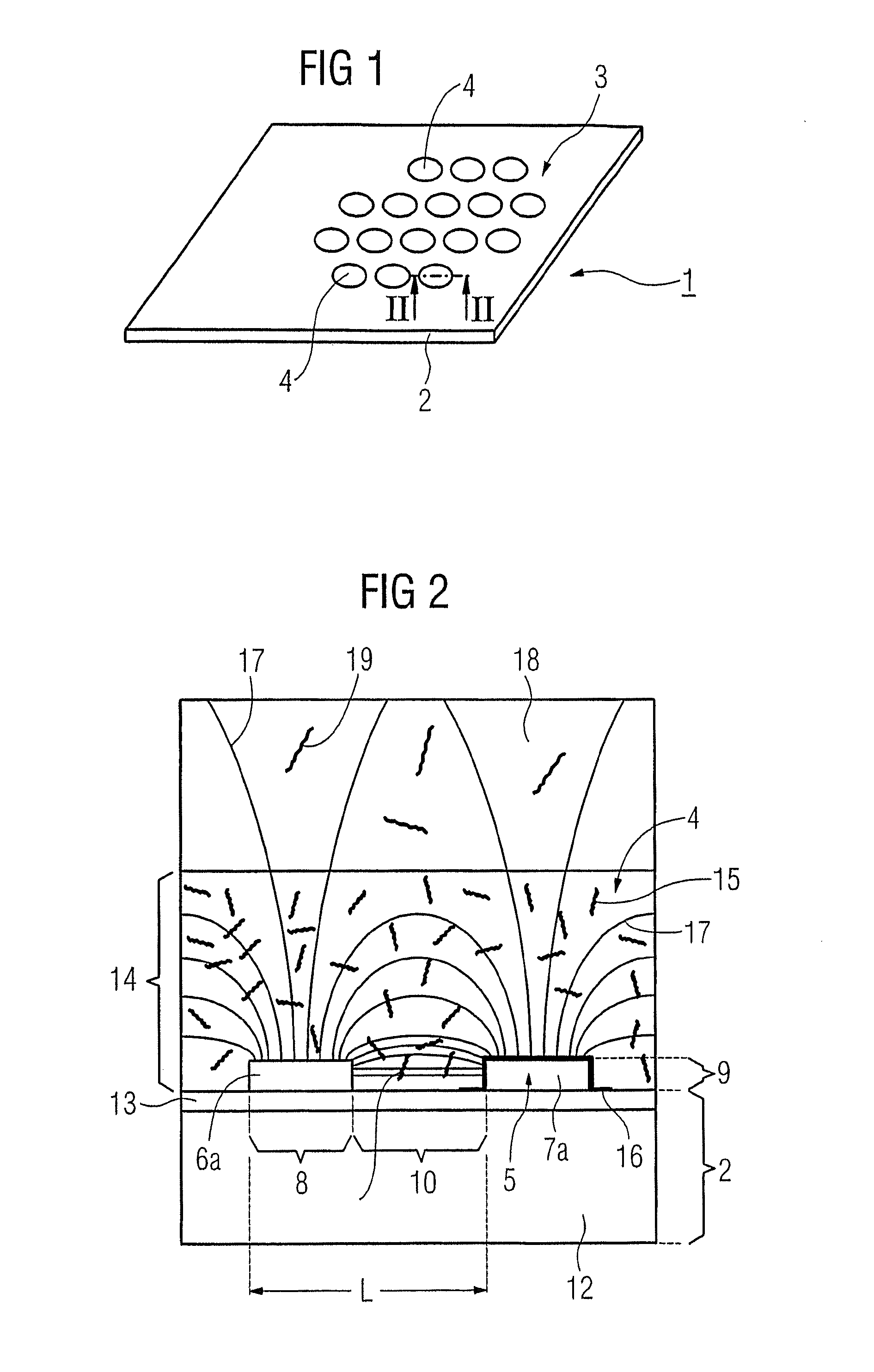
[0026]As shown in FIG. 1, a biochip 1 includes a flat carrier 2, on one side of which a spot array 3 is applied. A spot 4 contains immobilized catcher molecules, for example oligonucleotides. If an analyte solution with unknown target molecules is applied to a spot, then the target molecule is coupled to the catcher molecule in the event of corresponding matching in the base sequence. The property change brought about by such a binding event, e.g., changes in the resistivity or the dielectric constant, is detected preferably impedance-spectroscopically by way of an electrode arrangement 5. However, it is also possible to detect such binding events electrically by means of the electrode arrangement 5 in any other manner directly or indirectly, e.g., via a redox reaction or agent or the like.

[0027]A 2-pole electrode arrangement is present in the case of the example embodiment of FIG. 2. This arrangement is applied to the flat carrier 2 for example with the aid of a photolithographic m...


PUM


Abstract

A biochip includes a flat carrier and an array of spots containing catcher molecules which are arranged on the carrier. Each spot is associated with a microelectrode arrangement for impedance spectroscopic detection of binding events occurring between the catcher molecules and the target molecules applied via an analyte solution. In order to increase the sensitivity or the binding-specific measuring effects of the bio-chip, the electrode arrangement is at least partially embedded in a hydrophilic reaction layer containing catcher molecules and which is permeable to target molecules.

Description

CROSS REFERENCE TO RELATED APPLICATION[0001]This application is a continuation-in-part of U.S. patent application Ser. No. 10 / 540,208, filed Nov. 16, 2005, as a National Phase of PCT Application PCT / DE2003 / 004137, filed Dec. 15, 2003, which claims priority based on German Patent Application No. DE 102 598 21.5 filed in Germany on Dec. 19, 2002, the entire contents of which is hereby incorporated herein by reference.BACKGROUND OF THE INVENTION[0002]1. Field of the Invention[0003]The invention generally relates to a biochip, in particular a DNA chip.[0004]2. Description of Related Art[0005]Biochips or DNA chips include a flat carrier, on one side of which at least one spot array, that is to say a grid-shaped arrangement of analysis positions, is present. The spots contain probe or catcher molecules, for example oligonucleotides, immobilized on the carrier surface. Target molecules, for example DNA fragments, contained in an analyte solution applied to a spot couple to the catcher mole...

Claims


Application Information

Patent Timeline
IPC IPC(8): G01N33/543
CPCG01N33/543G01N27/026G01N33/5438C12M1/34
Inventor GUMBRECHT, WALTERSTANZEL, MANFRED
Owner BOEHRINGER LNGELHEIM VETMEDICA GMBH
Why Eureka
Try Eureka