Data Centre

a data centre and data technology, applied in data processing centers, building repairs, parkings, etc., can solve the problems of time-consuming installation of m&e services, and achieve the effect of high-efficiency production lines, cost and environmental advantages

Active Publication Date: 2014-10-09
BRIPCO
View PDF38 Cites 33 Cited by
  • Summary
  • Abstract
  • Description
  • Claims
  • Application Information

AI Technical Summary

Benefits of technology

[0045]Thus, in an embodiment of the invention the components of a data centre may be manufactured remotely from the site where the data centre is to be located, and furthermore, substantially all of the services (including the necessary mechanical and electrical apparatus) required for the operation of the data centre may be installed onto the ceiling portion and tested at this stage. There is no need to assemble the data centre components into a data centre in the factory, which clearly allows for a highly streamlined production line. The data centre components, with the services already fitted, can then be packaged into a volume small enough that several packag

Problems solved by technology

Thirdly, the use of a single chassis to provide multiple services is a compact and efficient solution which speeds assem

Method used


Image

  • Data Centre
  • Data Centre
  • Data Centre

Examples


first embodiment

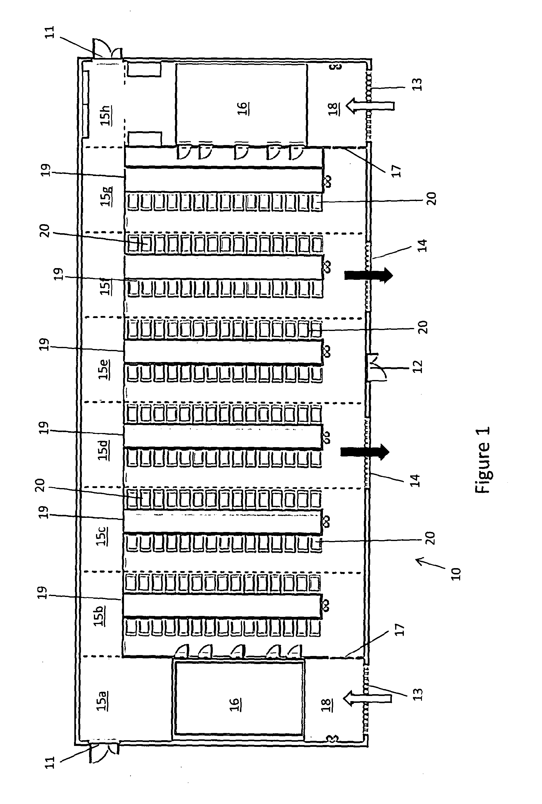
[0075]FIG. 1 shows the layout of a data centre building 10 according to the invention. At either end of the building 10 there is an entrance, 11. At the front of the building there is a fire exit 12. Also at the front of the building are two ambient air intake holes 13. Each ambient air intake 13 contains a set of controllable louvres which enable the amount of ambient air that is allowed into the building to be controlled. Ambient air entering the building is denoted by the white arrows. Between the two ambient air intakes 13 there are two holes defining a pair of exhaust air outlets 14. Exhaust air outlets 14 also each contain a set of controllable louvres. Exhaust air exiting the building is denoted by the black arrows.

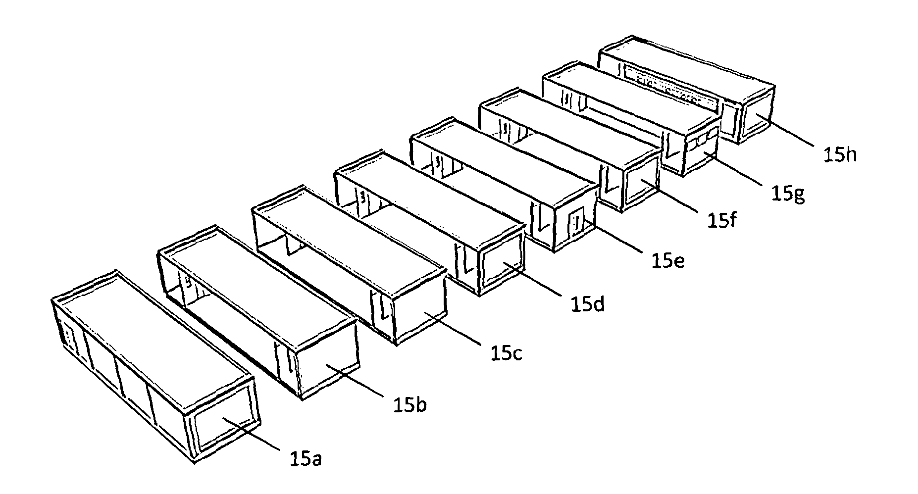
[0076]The data centre building 10 is made up of eight sections 15a-h, with the joins between adjacent sections shown by dotted lines. The short ends of the rectangular sections form the front and back external side walls of the building. The left-hand side of secti...

second embodiment

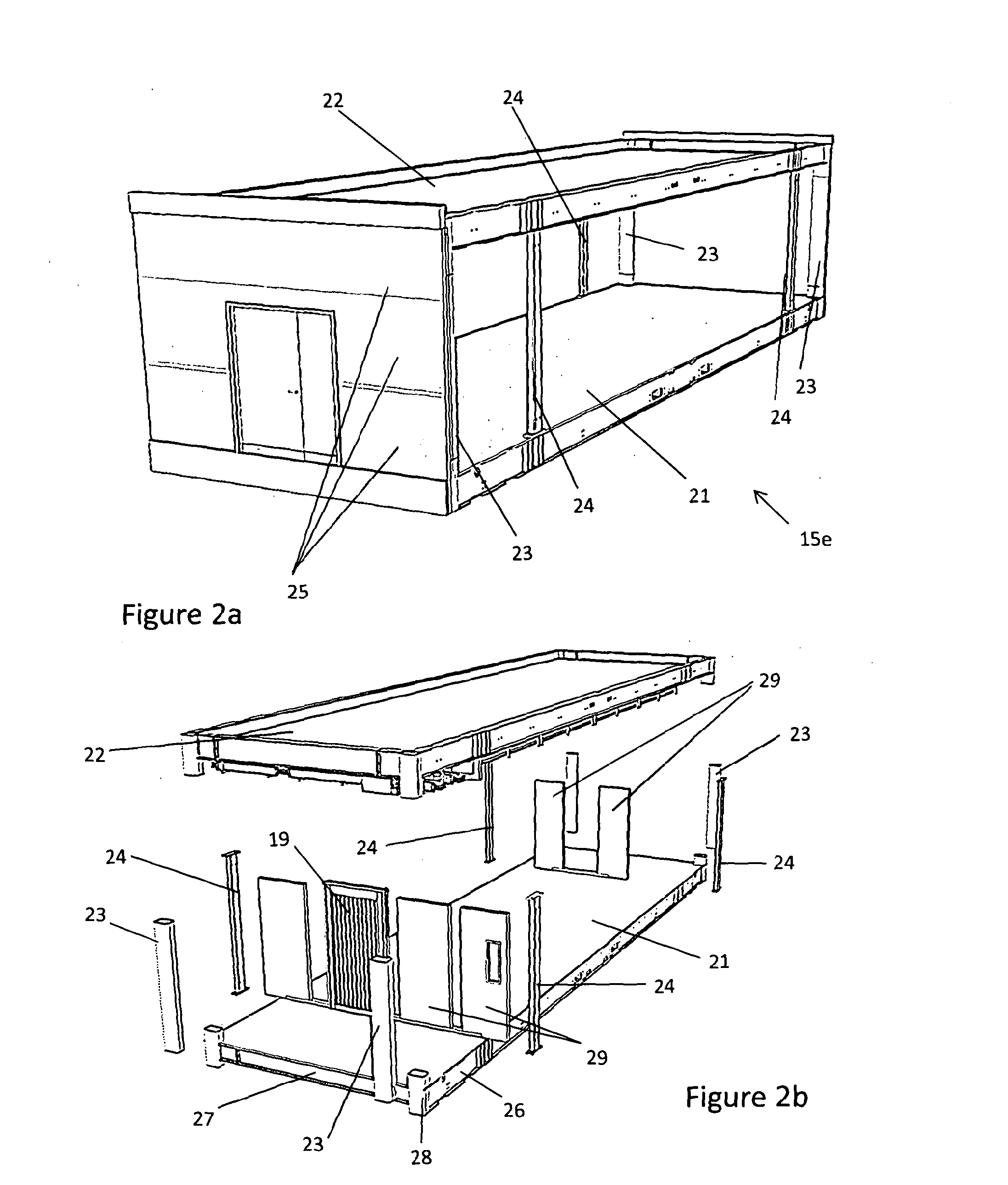
[0124]In this second embodiment the ceiling portions 222 of the ground floor storey also serve as the floor portions 221 of the sections immediately above. This does not require any alteration to the basic structure of the ceiling portion; rather it is simply a matter of fixing flooring material to the top of the ceiling section 222 rather than roofing material. Thus, as shown in FIGS. 16a and 16b, the ceiling portion 222 comprises a framework consisting of two long side steel beams 226, two short end steel beams 227, and four steel corner elements 228, which are designed to connect with the ground floor corner posts 223a (shown in FIG. 16a) which support the ceiling portion 222. The lower surface (not visible) of the ceiling portion 222 is made from steel plate with a plastic coating finish.

[0125]On top of the ceiling portion 222, the floor 221 is defined by means of a plywood floor deck supported on the joists of ceiling portion 222.

[0126]In this second embodiment, the corner elem...


PUM


Abstract

A data centre comprises a plurality of sections (15a-15h) assembled together to define a unitary structure (10) such that there exists at least one personnel area that spans at least two sections; wherein the sections comprise a first section with which there is associated a first service—carrying chassis (40, 50, 60, 70) and a second section with which there is associated a second service—carrying chassis 40, 50, 60, 70), each of the first and second service—carrying chassis comprising a frame (41, 51, 61, 71) onto which is mounted components of at least two different services (42-44, 46); the first and second chassis are connected to each other by means of a junction (47) between the first and second chassis; and the first and second sections each include a ceiling (22) and the first service carrying chassis is mounted on the ceiling of the first section and the second service carrying chassis is mounted on the ceiling of the second section.

Description

FIELD OF THE INVENTION[0001]The present invention concerns data centres and a method of constructing a data centre. More particularly, but not exclusively, this invention concerns data centre buildings, for example provided in sectional form. The invention also concerns a kit of parts for constructing a data centre.BACKGROUND OF THE INVENTION[0002]A data centre is a late 20th Century development that has grown as a response to the increasing demand for computer processing capability and a recognition of the importance of IT in the place of every business and organisation today. Whereas smaller organisations have sufficient processing power with laptops, PCs and occasionally servers, larger organisations require higher capacity centralised processing to serve a wide range of needs and applications. A few years ago this capacity was supplied by large mainframe computers, but more recently the method used has been to provide data centres comprising many networked computer servers known...

Claims


Application Information

Patent Timeline
IPC IPC(8): H05K7/14E04H1/12E04H1/00
CPCH05K7/1497E04H1/12E04H1/005E04B1/343E04B1/34315E04H2005/005Y02B20/40E04B1/34317E04B1/34869E04H5/00H05K7/1489H05K7/1492H05K7/1495
Inventor ROGERS, PAUL
Owner BRIPCO
Why Eureka
Try Eureka