
Exhaust leakage management

a technology for exhaust and leakage management, applied in the direction of combustion engines, charge feed systems, non-fuel substance addition to fuel, etc., can solve the problems of difficult management of possible undesirable exhaust byproducts, negative influence on other engine characteristics, etc., and achieve the effect of reducing emissions

Active Publication Date: 2014-10-09
FORD GLOBAL TECH LLC
View PDF15 Cites 4 Cited by
  • Summary
  • Abstract
  • Description
  • Claims
  • Application Information

AI Technical Summary

Benefits of technology

The exhaust gas management arrangement described in this patent text aims to reduce emissions from an engine. One technique for reducing nitrogen oxides (NOx) emissions is Exhaust Gas Recirculation (EGR) where some cooled exhaust gas is recirculated back to the engine's combustion chamber(s). Another technique is to add a turbocharger to increase power output. However, this can make the management of possible undesirable exhaust byproducts more difficult. The patent proposes an exhaust gas management system that includes a port to capture leaked exhaust gas from a movable portion of an exhaust gas flow directing mechanism and a passage to direct the leaked exhaust gas to the crankcase of the engine. This system also includes a fluid path to manage and handle the leaked exhaust gas instead of releasing it into the atmosphere. The technical effect of this invention is to reduce emissions and manage exhaust gases in an efficient way.

Problems solved by technology

But, an advantageous technique applied to one part of the engine may negatively affect other engine characteristics by introducing complexity and / or additional components.
However, including a turbocharger in an engine may make the management of possible undesirable exhaust byproducts more difficult.

Method used


Image

  • Exhaust leakage management
  • Exhaust leakage management
  • Exhaust leakage management

Examples


Embodiment Construction

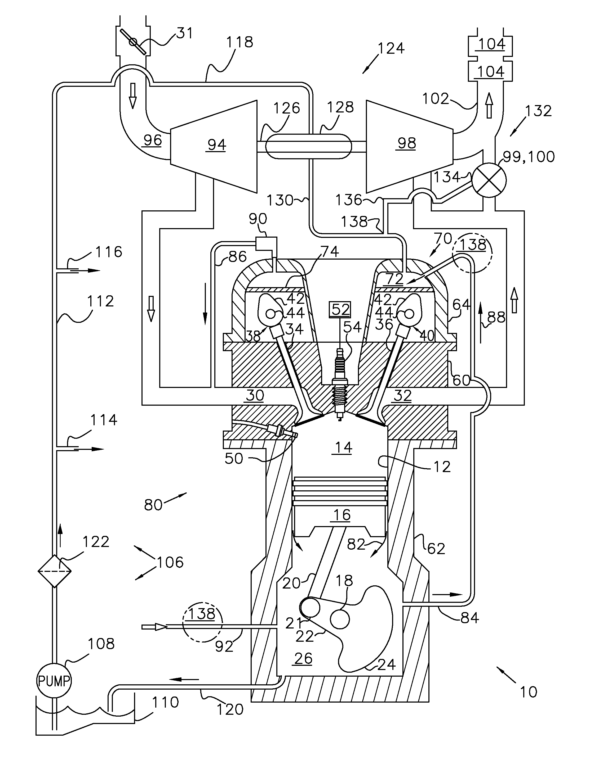
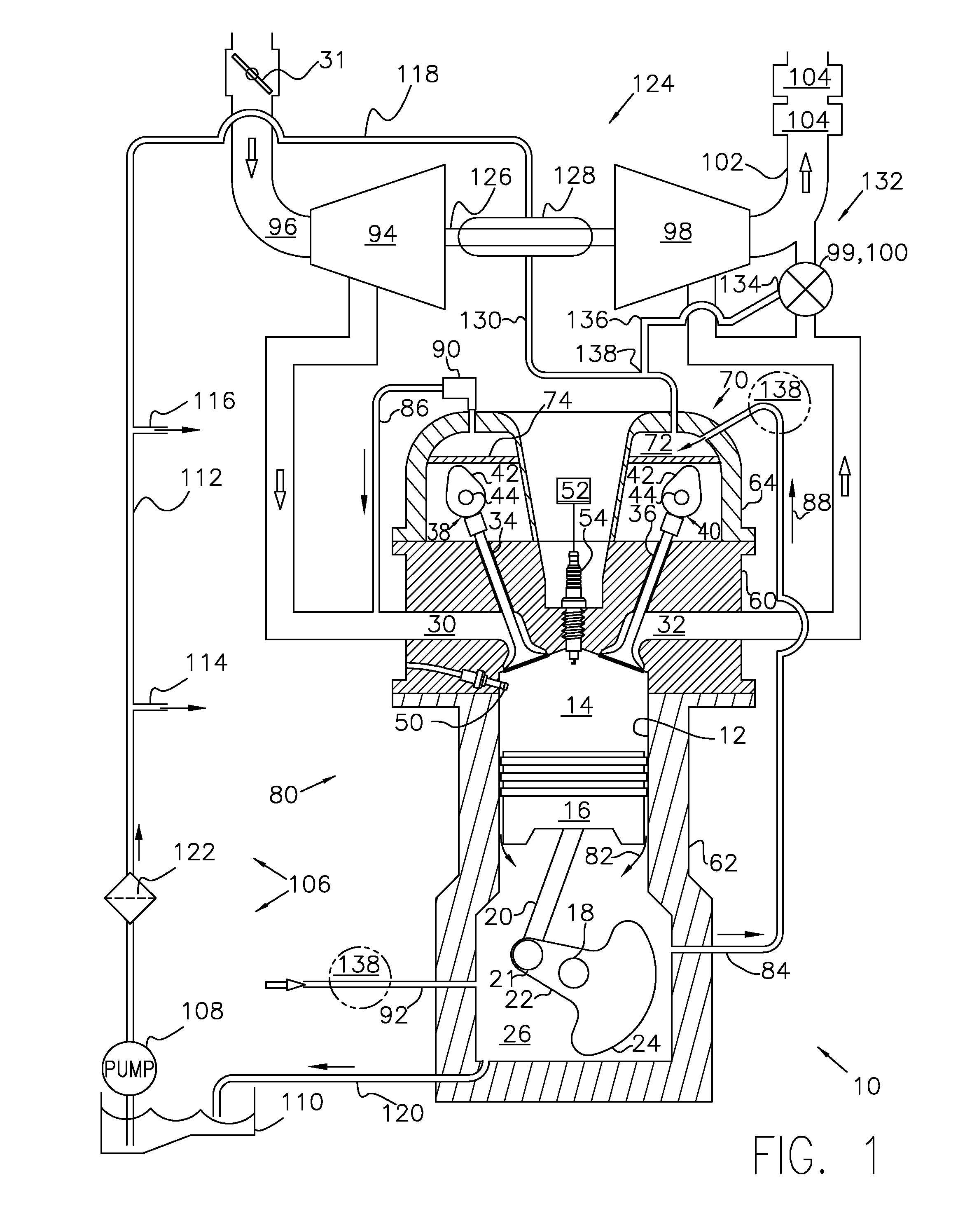
[0013]FIG. 1 is a cross-sectional diagram illustrating a cross-section of an engine 10 in accordance with the present disclosure. Various features of the engine may be omitted, or illustrated in a simplified fashion for ease of understanding of the current description. For example, areas may include continuous cross hatching that may otherwise indicate a solid body, however actual embodiments may include various engine components, and / or hollow, or empty, portions of the engine with the cross hatched areas.

[0014]FIG. 1 is a cross-sectional view through one cylinder 12 of the engine 10. Various components of the engine 10 may be controlled at least partially by a control system that may include a controller (not shown), and / or by input from a vehicle operator via an input device such as an accelerator pedal (not shown). The cylinder 12 may include a combustion chamber 14. A piston 16 may be positioned within the cylinder 12 for reciprocating movement therein. The piston 16 may be cou...


PUM


Abstract

Embodiments may provide an exhaust gas management arrangement for an engine. The exhaust gas management arrangement may include a port disposed to capture an exhaust gas leaked from a movable portion of an exhaust gas flow directing mechanism. The arrangement may also include a passage to direct the leaked exhaust gas to a crankcase of the engine.

Description

FIELD[0001]The present application relates to controlling, and / or managing possible exhaust gas leaks from various engine components and directing the leaks to a crankcase ventilation system for more advantageous handling.BACKGROUND AND SUMMARY[0002]Internal combustion engines often include techniques to improve various engine characteristics. But, an advantageous technique applied to one part of the engine may negatively affect other engine characteristics by introducing complexity and / or additional components.[0003]One example technique for reducing nitrogen oxides (NOx) emissions from engine exhaust; formed when nitrogen and oxygen in the intake air is subjected to high combustion temperatures; is Exhaust Gas Recirculation (EGR) wherein a portion of cooled exhaust gas is recirculated back to the engine's combustion chamber(s) and mixed with the intake air. Another technique to increase power output is to add a turbocharger by capturing the power of exhaust gases to drive a compre...

Claims


Application Information

Patent Timeline
IPC IPC(8): F02B37/18
CPCF02B37/183F01M13/028F02B39/14Y02T10/12F01M13/00
Inventor BIDNER, DAVID KARLHOUSE, CHRISTOPHERSTATELER, CHAD
Owner FORD GLOBAL TECH LLC
Learn More