Rotator member to be fixed to rotary shaft of rotary electric machine, rotator including rotator member, and method for manufacturing rotary electric machine and rotator

a technology of rotator and rotor shaft, which is applied in the direction of manufacturing stator/rotor body, magnetic circuit rotating parts, and shape/form/construction of magnetic circuits, etc., can solve the problems of ring-shaped magnets cracking, failure of high speed rotation, and difficulty in providing a larger electric motor by providing a larger torqu

Active Publication Date: 2014-10-09
FANUC LTD
View PDF5 Cites 26 Cited by
  • Summary
  • Abstract
  • Description
  • Claims
  • Application Information

AI Technical Summary

Benefits of technology

[0012]Preferably, the tapered surface of the sleeve is a single linearly tapered surface, or includes a plurality of linearly tapered surfaces connected each other and inclined with respect to an axis of rotation at different angles from each other. The sleeve has a thick side that has a smaller diameter by the tapered structure. The thick side is preferably provided with an end portion to be sufficiently pressed by a press tool during a press fitting process. The end portion in the sleeve is thus thick, which allows an increased press fitting force to be applied to the end portion during a press fitting operation. The end portion of the sleeve preferably has a taper angle of 0° such that the end portion has an inner diameter that is constant.
[0016]A rotator according to another aspect of the present invention includes a rotary shaft having an outer circumference surface expanding radially outward as extending in a direction from an axially first side toward an axially second side, and the rotator member described above, in which the sleeve is fixed to the rotary shaft on a radially outside of the rotary shaft, so that the second end of the sleeve is positioned to the axially second side of the rotary shaft relative to the first end of the sleeve. Since this structure requires no oil pressure fitting, no holes for oil are needed in the sleeve. Therefore, it is possible to avoid stress concentration around the holes, thereby advantageously provide increased maximum rotation speed.
[0018]A substantially entire area (for example, more than 90%) of the inner circumference surface of the sleeve and the outer circumference surface of the rotary shaft are brought into a surface-to-surface contact for an axial distance where the tubular member is disposed. This structure provides a wider contact area (e.g. a region of more than 90%) between the inner circumference surface of the sleeve and the outer circumference surface of the rotary shaft to thereby reduce the pressing force between the surfaces, resulting in an easy press fitting operation between them. In consideration of convenient disassembling, a minimum groove may be provided to deliver lubricant oil to their surfaces under contact. In such a structure, the same value of at least more than 90% may be applied to the area that the surfaces are contacted and fixed with each other. Preferably, the sleeve deforms beyond its elastic deformation zone. A rotary electric machine according to another aspect of the present invention includes the rotator described above.
[0020]With any stress concentration applied, the maximum rotation speed of the rotator is restrained by its limiting stress. Therefore, a structure to generate stress concentration is preferably excluded. Accordingly, the hole communicating between the outer circumference surface of the rotator and the radially inner surface of the rotary sleeve disclosed in the Patent Literature 1 mentioned above is not preferably provided. Exclusion of the hole avoids stress concentration and can further increase a rotation speed.
[0023]The step of fixing the rotator member by an interference fitting includes fitting the sleeve over the rotary shaft from a side of the axially first side so that the second end of the sleeve is positioned at the axially second side relative to the first end; press fitting the sleeve over the rotary shaft so as to push the first end of the sleeve to the axially second side; and causing the sleeve to expand radially outward by the force of press fitting the sleeve, while the sleeve is press fitted to a predetermined fixing position.
[0024]Preferably, the rotator member includes a gap at least partially between the sleeve and the magnet segments. In the step of fixing the rotator member by the interference fitting, the outer circumference surface of the sleeve and the inner circumference surfaces of the magnet segments are brought into a surface-to-surface contact in their almost entire areas by causing the sleeve to expand radially outward so as to fill the gap.

Problems solved by technology

The ring-shaped magnets disclosed in abovementioned Patent Literature 1 are under the limitation of upsizing due to a manufacturing restriction which makes it difficult to provide a larger electric motor by which a larger torque is provided.
Furthermore, when the ring-shaped magnets are fitted over a magnetic ring and fixed to a rotary shaft with a significantly large interference for prevention of looseness during a high speed rotation, the ring-shaped magnets may crack because of expansion of the magnetic ring due to the significantly large interference.
On the contrary, an interference arranged to a degree so as not to crack the ring-shaped magnets does not provide a sufficiently large interference to the magnets and the magnetic ring, which presents the magnets and the magnetic ring an idle running, resulting in improperly low torque in a high speed rotation zone or a failure of a high speed rotation.
Use of this method requires a complicated large manufacturing apparatus with complex and more difficult operations, which causes a problem of reduced manufacturing efficiency.
However, a high speed rotation operation generates a stress concentration around the hole, and the maximum stress restrains the rotation from reaching the maximum speed.
Moreover, the hole has to be precisely balanced, disposed and formed in consideration of the balance of the rotary shaft, which leads to a cause of an increased manufacturing cost.
The machining after completion of the rotator, however, is a risky process more than an increase of a simple process, which requires an attention to the magnetic attraction of the permanent magnets during the processing and a possible chemical damage to the rotator body itself caused by a cutting liquid.
Therefore, such an operation has a problem of being significantly costly.
Specifically, with only the fitting force of the sleeve with respect to the rotary shaft remaining at the maximum rotation speed, there is a problem that the magnets and the sleeve may slide in the rotational direction under increased load.

Method used


Image

  • Rotator member to be fixed to rotary shaft of rotary electric machine, rotator including rotator member, and method for manufacturing rotary electric machine and rotator
  • Rotator member to be fixed to rotary shaft of rotary electric machine, rotator including rotator member, and method for manufacturing rotary electric machine and rotator
  • Rotator member to be fixed to rotary shaft of rotary electric machine, rotator including rotator member, and method for manufacturing rotary electric machine and rotator

Examples


Embodiment Construction

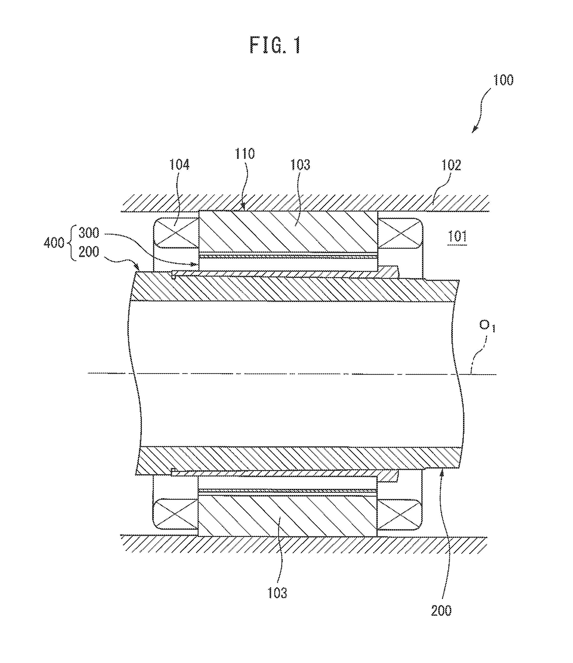
[0051]An embodiment of the present invention will be described below in detail with reference to the drawing. Firstly, a structure of an electric motor 100 according to an embodiment of the present invention will be described referring to FIG. 1. It should be noted that, in the following description, a direction extending along the central axis of a rotary shaft of the electric motor 100 is designated as an axial direction, and the left side on the paper of FIG. 1 is designated as an axially front side while the right side thereon is designated as an axially rear side. It should also be noted, however, that the axially front side and the axially rear side in the following description are defined for a point of view of an easy and convenient understanding of the invention, and are not intended to limit the directions, e.g., front side and rear side, of the electric motor.

[0052]The electric motor 100 includes a housing 102 that defines an inner space 101, a stator 110 statically dispo...


PUM

PropertyMeasurementUnit
rotation speedaaaaaaaaaa
taper angleaaaaaaaaaa
thicknessaaaaaaaaaa

Abstract

A rotator member 300 includes a tubular sleeve 301 having a first end surface and a second end surface, a plurality of magnet segments 311 circumferentially disposed at a radially outside of the sleeve 301, and a tubular member 321 adapted to cover the magnet segments 311 from a radially outside to hold the magnet segments 311 between the tubular member 321 and the sleeve 301. The sleeve 301 has an inner circumference surface that includes a tapered surface that gradually and outside the radial direction expands in a direction from the first end surface toward the second end surface.

Description

BACKGROUND ART[0001]1. Technical Field[0002]The present invention relates to a rotator member fixed to a rotary shaft of a rotary electric machine, a rotator including the rotator member, and a method for manufacturing the rotary electric machine and the rotator.[0003]2. Description of Related Art[0004]When an electric motor using permanent magnets as a rotator is rotated at a high speed, the electric motor has to be reinforced in order to endure centrifugal force generated during high speed rotation with respect to strength of the permanent magnets and a fixing structure of the magnets. In this case, generally speaking, such a reinforcement structure for covering the permanent magnets with a sleeve made of, for example, carbon fiber or titanium is provided. Japanese Laid-open Patent Publication No. 11-89142, for example, discloses a high speed synchronous motor provided with ring-shaped magnets including an outer circumference that is reinforced with carbon fiber reinforced plastic...

Claims


Application Information

Patent Timeline
Patent Type & Authority Applications(United States)
IPC IPC(8): H02K1/30H02K15/03H02K1/27
CPCH02K1/30H02K15/03H02K1/274H02K1/278H02K1/28Y10T29/49012
Inventor ARIMATSU, YOHEI
Owner FANUC LTD
Why Eureka
Try Eureka