Colored optical fiber, optical fiber ribbon and optical fiber cable

a technology of optical fiber and color, applied in the direction of cladded optical fibre, glass optical fibre, instruments, etc., can solve the problem of different stress applied to each optical fiber in the thickness direction and in the width direction

Inactive Publication Date: 2014-10-09
FURUKAWA ELECTRIC CO LTD
View PDF2 Cites 13 Cited by
  • Summary
  • Abstract
  • Description
  • Claims
  • Application Information

AI Technical Summary

Problems solved by technology

However, in fact the cross section of the optical fiber includes all sorts of asymmetry such as the cladding surface shape of the optical fiber cross-section deviating from a complete circle and concentricity error.
On the other hand, since the cross-section of an optical fiber ribbon is asymmetric in the thickness direction and the width direction, there is a problem that the stress applied to each optical fiber in the thickness direction is different from the stress in the width direction.

Method used


Image

  • Colored optical fiber, optical fiber ribbon and optical fiber cable
  • Colored optical fiber, optical fiber ribbon and optical fiber cable
  • Colored optical fiber, optical fiber ribbon and optical fiber cable

Examples


examples

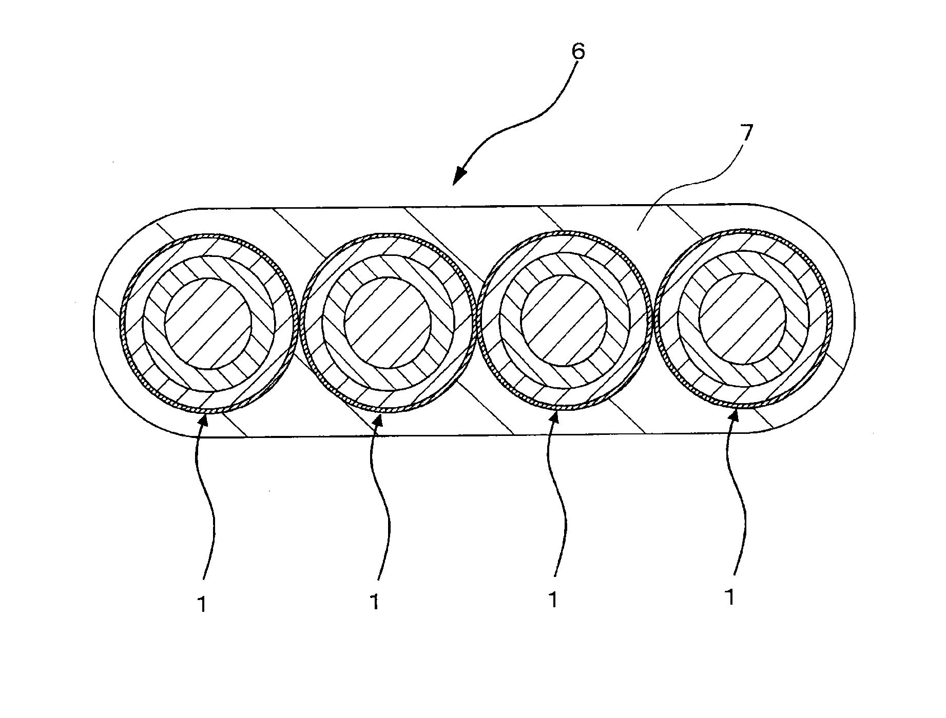
[0045]Hereinafter, the present invention will be described by way of Examples of the optical fiber ribbon 6 using the colored optical fiber 1, and the optical fiber cable 8 explained in the embodiments described above, but the present invention is not intended to be limited to the following examples.

[0046]Colored optical fibers 1 having the relaxation modulus varied by changing the kind or amount of incorporation of the material that constituted the coating layer in the colored optical fibers 1 such as described above, were obtained. Optical fiber ribbons 6 and optical fiber cables 8 were produced using these, and after the optical fiber ribbon and the cables were immersed in hot water at 60° C. for 90 days, the increases of the transmission loss were measured. Furthermore, the polarization-mode dispersion characteristics of the colored optical fibers 1 in the state of being accommodated in optical fiber cables were measured.

[0047]Next, the method for measuring the relaxation modulu...

examples 1 to 6

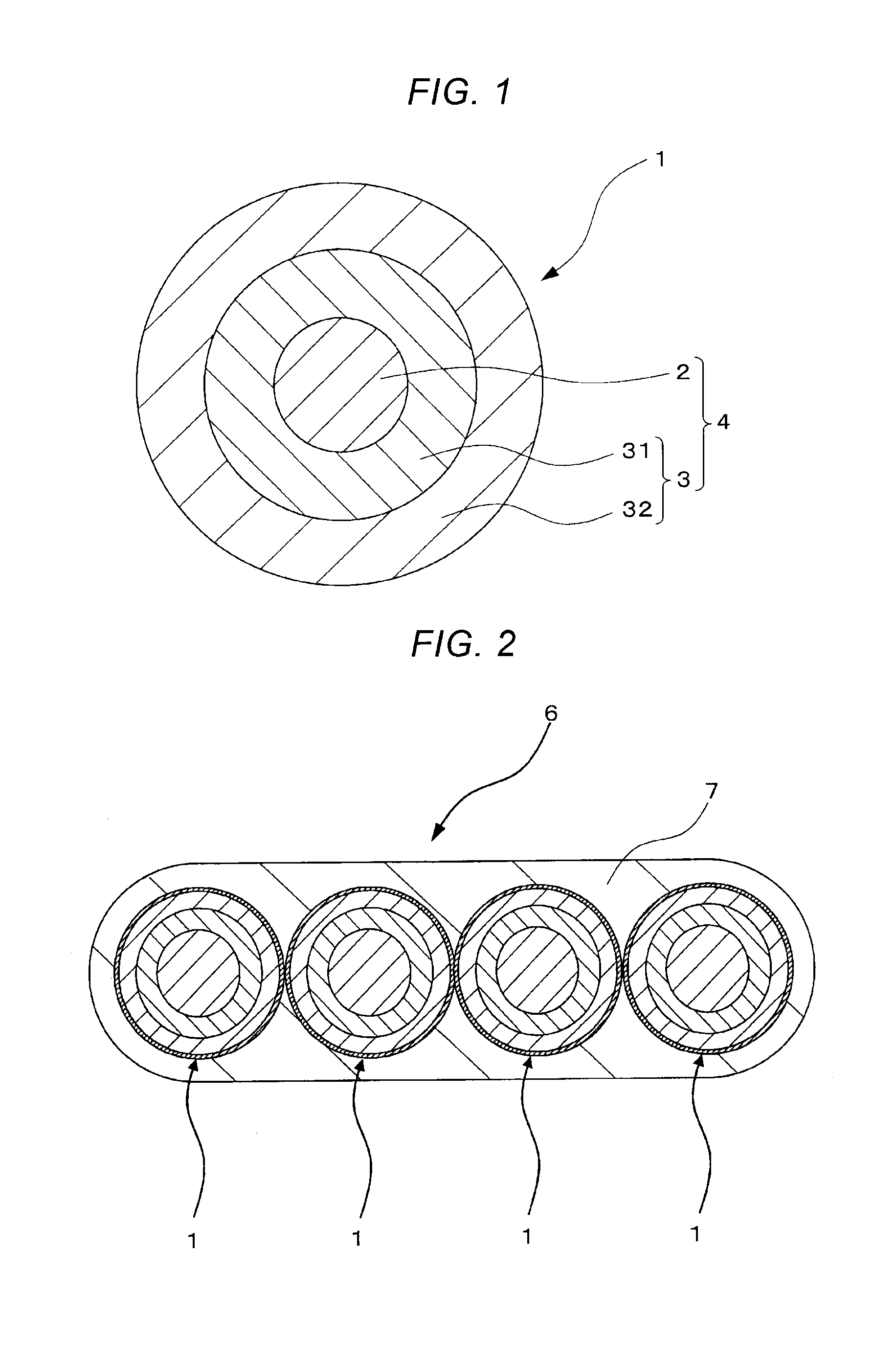
[0062]For the test specimen of Example 1, as illustrated in FIG. 1, a coated optical fiber was produced by forming a primary coating layer 31 having an outer diameter of 195 μm and a Young's modulus of 0.6 MPa on the circumference of a glass coated optical fiber 2 formed of quartz glass and having an outer diameter of 125 μm; and forming a secondary coating layer 32 having an outer diameter of 243 μm and a Young's modulus of 830 MPa on the circumference of the primary coating layer 31. Furthermore, a colored layer 5 was formed on the circumference of the secondary coating layer 32, and thus a colored optical fiber 1 having a three-layered coating structure having an outer diameter of 255 μm was produced. The primary coating layer 31 was produced using an UV curable resin that used urethane acrylate, and the secondary coating layer 32 was produced using an UV curable resin containing 2-ethylhexyl acrylate as a monomer. Also, in the colored layer 5, an UV curable resin was used as a c...


PUM

PropertyMeasurementUnit
Young's modulusaaaaaaaaaa
outer diameteraaaaaaaaaa

Abstract

A colored optical fiber including a glass optical fiber; a primary coating layer that covers the glass optical fiber; a secondary coating layer that covers the primary coating layer; and a colored layer that coats the secondary coating layer. The relaxation modulus after 24 hours at 60° C. of of the layers coated is 140 MPa or less.

Description

CROSS-REFERENCE TO RELATED APPLICATIONS[0001]This application is a continuation of PCT / JP2012 / 080673 filed on Nov. 28, 2012 which claims benefit of Japanese Patent Application No. 2011-286787 filed on Dec. 27, 2011, the subject matters of which are incorporated herein by reference in their entirety.FIELD OF THE INVENTION[0002]The present invention relates to a colored optical fiber, an optical fiber ribbon, and an optical fiber cable using the same.BACKGROUND OF THE INVENTION[0003]An optical communication technique has been required to strictly control a dispersion characteristics and long-term reliability for meeting the demand of increased communication capacity primarily needed by a wavelength division multiplexing in recent years. For this reason, an optical fiber cable has also been required to control a polarization-mode dispersion characteristics, or the increase of transmission loss on the occasion of use in a high temperature high humidity environment.[0004]An optical fiber...

Claims


Application Information

Patent Timeline
Patent Type & Authority Applications(United States)
IPC IPC(8): G02B6/44G02B6/02
CPCG02B6/4403G02B6/4409C03C25/285C03C25/1065G02B6/02395
Inventor TANAKA, HIROKISAITO, MINORUKASAHARA, MINORUNAKAJIMA, YASUOARASHITANI, YOSHIHIRO
Owner FURUKAWA ELECTRIC CO LTD
Why Eureka
Try Eureka