Gas turbine combustor

a technology of combustor and gas turbine, which is applied in the direction of machines/engines, combustion types, lighting and heating apparatus, etc., can solve the problems of unstable combustion of premixed gas, deterioration of flame stability of premixed flame, and oscillation of combustion, so as to reduce distance, reduce distance, reduce distance

Active Publication Date: 2014-10-16
MITSUBISHI POWER LTD
View PDF3 Cites 5 Cited by
  • Summary
  • Abstract
  • Description
  • Claims
  • Application Information

AI Technical Summary

Benefits of technology

The present invention aims to provide a gas turbine combustor that can improve the stability of a premixed flame and reduce the size of a low-temperature air layer formed between a pilot flame and the premixed flame. By doing so, the combustor can achieve better ignition and reduced combustion oscillation, resulting in a more stable and reliable gas turbine operation.

Problems solved by technology

In the above-described conventional gas turbine combustor 1, because a cooler pilot air layer (hereinafter referred to as “low-temperature air layer”) formed downstream of the flame stabilizer 9 inhibits the formation of the stable premixed flame, a problem that has been pointed out is that the flame stability of the premixed flame is deteriorated, which is one factor causing combustion oscillation.
Because this low-temperature air layer is an air layer having low temperature, it deteriorates the ignition with which the pilot flame forms the premixed flame by combusting the premixed gas; as a result, the combustion of the premixed gas will become unstable.
Accordingly, in the gas turbine combustor 1, it is not possible to form a stable premixed flame; therefore, the flame stability of the premixed flame is deteriorated, causing combustion oscillation.

Method used


Image

  • Gas turbine combustor
  • Gas turbine combustor
  • Gas turbine combustor

Examples


first embodiment

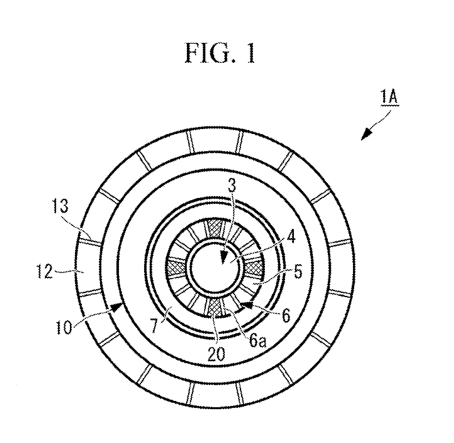
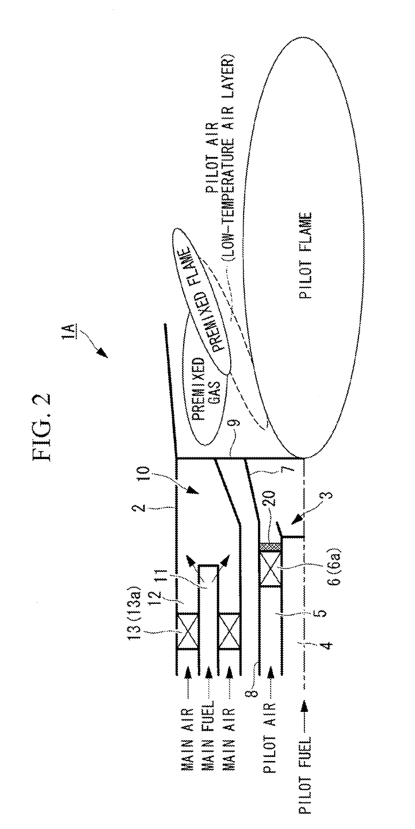
[0065]A gas turbine combustor 1A shown in FIG. 1 and FIG. 2 has a configuration in which a pilot burner 3 is provided at the center position of a combustor main body 2 formed in a cylindrical shape, and a plurality of (for example, eight) main burners 10 are provided at a uniform pitch in the circumferential direction so as to surround the periphery of this pilot burner 3.

[0066]The pilot burner 3 is provided with a pilot nozzle 4 that supplies pilot fuel and a pilot air channel 5 that is formed around the pilot nozzle 4 and supplies pilot air thereto. The pilot fuel supplied through the pilot nozzle 4 is combusted with the pilot air supplied from the pilot air channel 5 and, as shown in FIG. 2 for example, forms a pilot flame extending rearward of a flame stabilizer 9 from the combustor axial center.

[0067]A pilot swirler 6 that makes the flow of the pilot air become a swirling flow is disposed inside the above-described pilot air channel 5. This pilot swirler 6 partitions the interi...

second embodiment

[0078]Next, for the gas turbine combustor according to the present invention, a second embodiment will be described based on FIG. 4 and FIG. 5. Note that, in the following description, parts similar to those in the above-described embodiment are assigned the same reference numerals, and a detailed description thereof will thus be omitted.

[0079]In this embodiment, a gas turbine combustor 1B is provided with one or a plurality of plate-like projecting members 21 projecting rearward from the outer edge of the pilot cone 7 as the ignition improving part. In the illustrated configuration, four plate-like projecting members 21 arranged at a 90-degree pitch in the circumferential direction are provided so as to project from the rear end of the pilot cone 7 towards the rear flame forming region. In other words, the cylindrical member 8 of this embodiment employs the pilot cone 7 having plate members 21 at the rear end.

[0080]By attaching such plate-like projecting members 21, the flow of the...

third embodiment

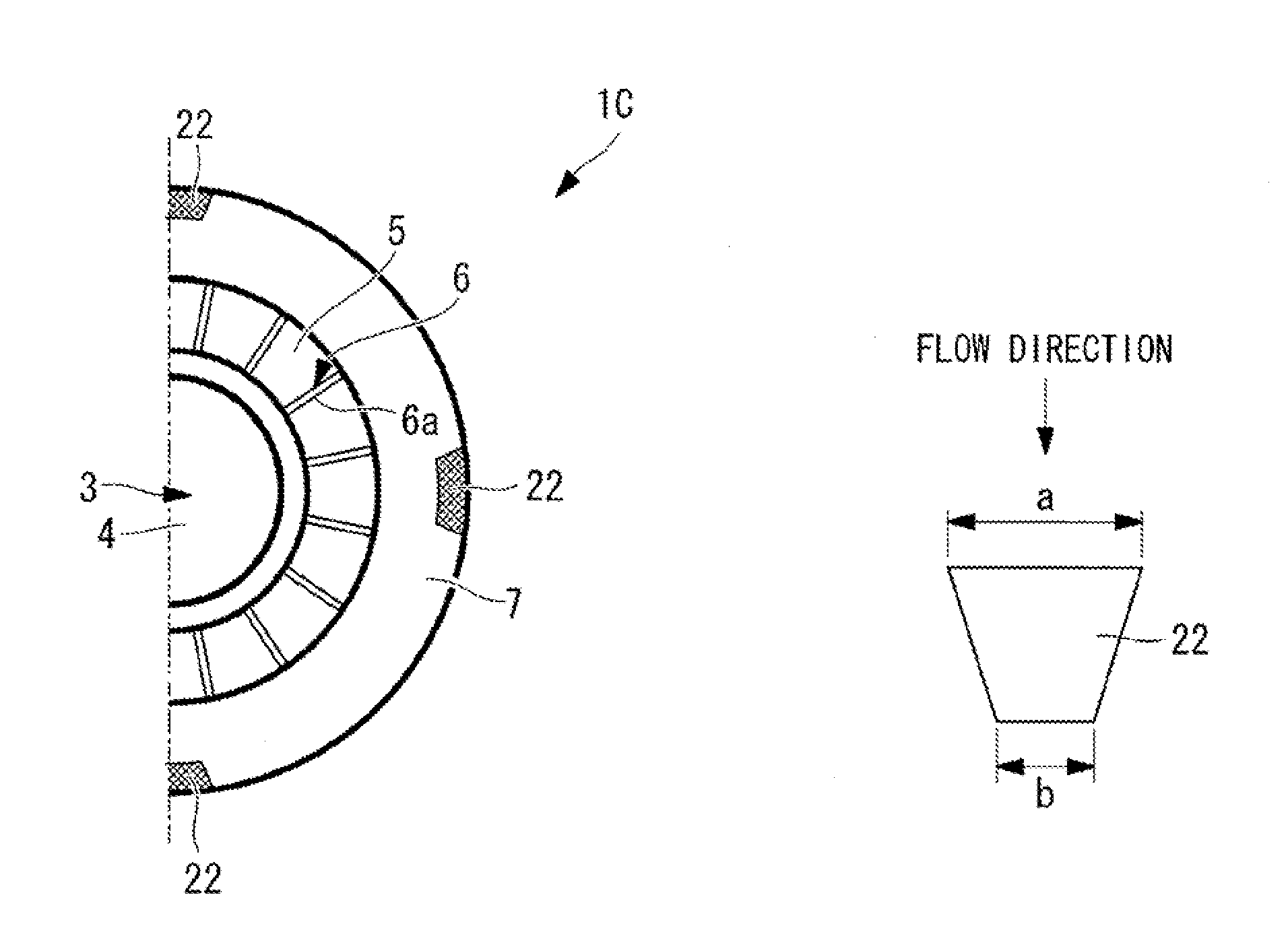
[0083]Next, for the gas turbine combustor according to the present invention, a third embodiment will be described based on FIG. 6A to FIG. 6C. In a gas turbine combustor 1C in FIG. 6A used here, the outer peripheral side main burner is omitted, and only the pilot burner is illustrated. Note that, in the following description, parts similar to those in the above-described embodiments are assigned the same reference numerals, and a detailed description thereof will thus be omitted.

[0084]In this embodiment, as the ignition improving part, wedge-shaped vortex generators 22 having a sweepback angle are provided at one or a plurality of positions on the inner peripheral surface of the locations corresponding to the outer edge of the pilot cone 7. In the illustrated configuration, four wedge-shaped vortex generators 22 arranged at a 90-degree pitch in the circumferential direction are provided on the inner peripheral surface of the outer edge of the pilot cone 7. In other words, the cylin...


PUM


Abstract

Provided is a gas turbine combustor capable of reducing the size of a low-temperature air layer of pilot air formed between a pilot flame and a premixed flame and of improving the flame stability of the premixed flame. A gas turbine combustor, which is provided with a pilot burner that is provided at the center portion of a combustor main body formed in a cylindrical shape to form a pilot flame, and a plurality of main burners arranged so as to surround the outer periphery of the pilot burner to form a premixed flame, includes, as the ignition improving part, a channel blocking member that reduces the size of the low-temperature air layer of the pilot air formed between the pilot flame and the premixed flame.

Description

CROSS-REFERENCE TO RELATED APPLICATIONS[0001]This application is a Divisional of copending U.S. application Ser. No. 12 / 666,673 filed on Dec. 24, 2009, and wherein U.S. application Ser. No. 12 / 666,673 is a national stage application filed under 35 U.S.C. §371 of International Application No. PCT / JP2008 / 073177, filed on Dec. 19, 2008, which is based upon and claims priority under 35 U.S.C. §119(a) to Japan Patent Application No. 2007-329955 filed on Dec. 21, 2007, the entire contents of which are hereby incorporated by reference.TECHNICAL FIELD[0002]The present invention relates to a gas turbine combustor.BACKGROUND ART[0003]As shown in FIG. 12 for example, as a conventional gas turbine combustor 1, there is one having a structure in which a pilot burner 3 is arranged at the center position of a combustor main body 2 formed in a cylindrical shape, and a plurality of (for example, eight) main burners 10 are arranged at a uniform pitch in the circumferential direction so as to surround...

Claims


Application Information

Patent Timeline
Patent Type & Authority Applications(United States)
IPC IPC(8): F23D14/70
CPCF23D14/70F23R3/286F23R3/343
Inventor INOUE, KEISAITO, KEIJIROMATSUMURA, YOSHIKAZUNAKAMURA, SOSUKE
Owner MITSUBISHI POWER LTD
Why Eureka
Try Eureka