System and process for natural gas liquefaction

a natural gas and liquefaction technology, applied in the field of natural gas liquefaction system and process, can solve the problems of limited lng productivity and achieve the effect of increasing the lng production ra

Active Publication Date: 2014-10-16
KEPPEL OFFSHORE & MARINE TECH CENT PTE LTD
View PDF10 Cites 10 Cited by
  • Summary
  • Abstract
  • Description
  • Claims
  • Application Information

AI Technical Summary

Benefits of technology

[0004]The present invention provides an LNG production system and method capable of achieving an increased LNG production rate without increasing the Refrigerant Compressor driver size and capacity.
[0005]The aim of this present invention is to provide a modified nitrogen expander cycle based LNG process, with an improved LNG production rate, which is limited by the size of the driver for main refrigerant compressor, typically Gas turbine for offshore. In the mean time, the LNG liquefaction efficiency is also improved. With the addition of an independently-operated chiller into the nitrogen expander cycle after the gas turbine driven compressor or expander driven compressor, the LNG production rate can be increased without increasing the driver size and capacity.
[0006]In one aspect, embodiments of the present invention provide a process for liquefaction of a natural gas. The process includes cooling the natural gas with a first refrigerant provided by a first cooling system and cooling the natural gas with a second refrigerant provided by a second cooling system. The second cooling system is a single phase cooling system. The first and second cooling systems operate independently from each other. The second refrigerant is cooled with the first refrigerant such that the cooling capacity of the second refrigerant and the second cooling system is increased.

Problems solved by technology

Compared to on-shore environment, offshore production of LNG faces many restrictions under which, the LNG productivity is limited.
One of these restrictions is due to the size and capacity of Refrigerant Compressor driver (typically gas turbine) used in expander-based LNG process.

Method used


Image

  • System and process for natural gas liquefaction
  • System and process for natural gas liquefaction
  • System and process for natural gas liquefaction

Examples


Embodiment Construction

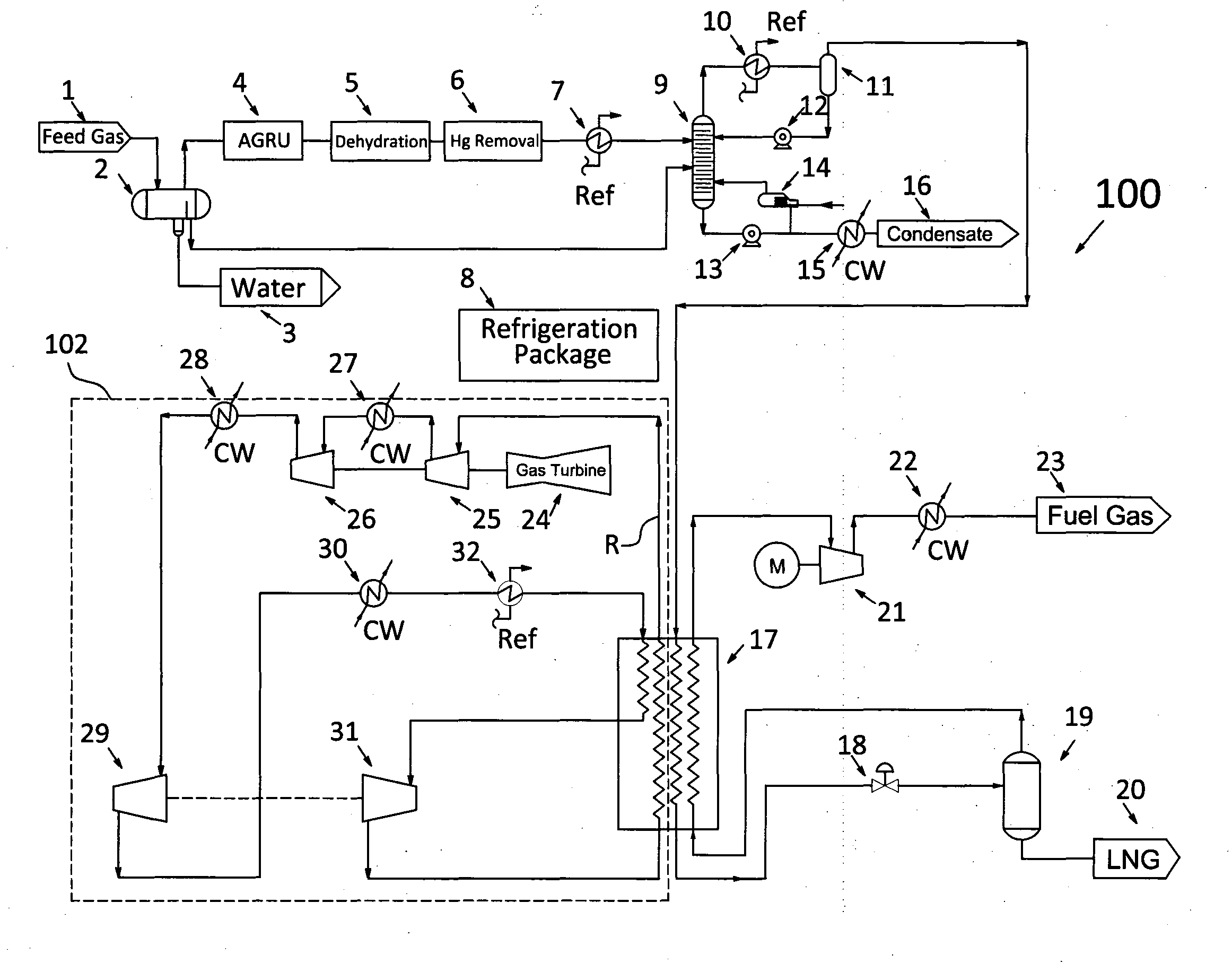
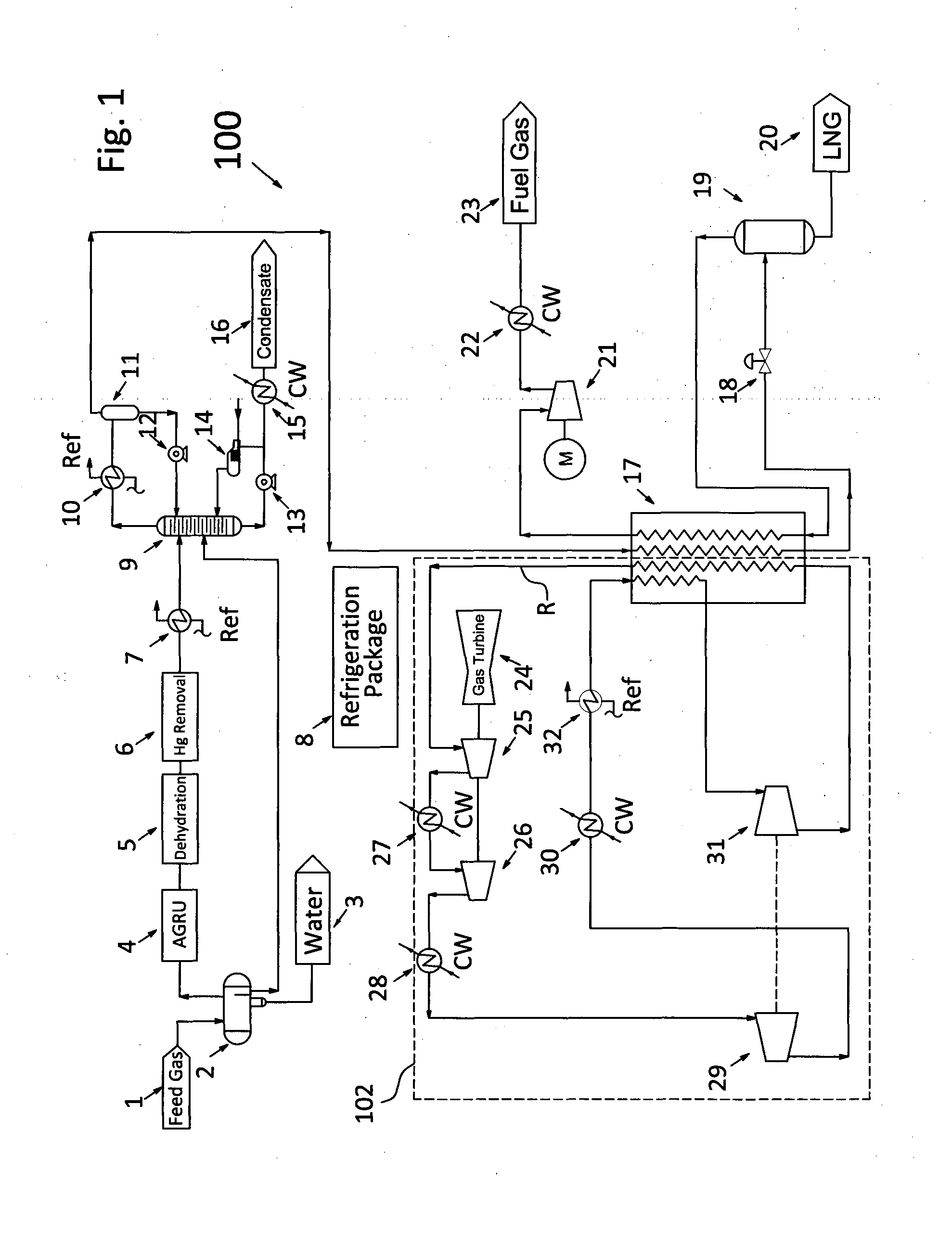
[0014]FIG. 1 shows a natural gas liquefaction system and process 100 according to one embodiment of the present invention. Natural gas 1 flows into the liquefaction process from the offshore production facility. This natural gas is typically stranded gas or associated gas, and has undergone various degrees of treatment. The present description will address the case when the feed gas from a crude stabilization unit is at a pressure in the range of about 20 bar to about 60 bar, or has been compressed to a pressure in the range of about 20 bar to about 60 bar in oil production gas compressors. The offshore feed gas normally contains methane in the range of from about 70% to about 90%; ethane of about 6-10%, with typical pressure of 20-60 bar.

[0015]The feed natural gas 1 firstly enters a feed gas receiver 2 which may be a three phase separator, if a liquid water phase is present in feed natural gas 1. The vapour from the gas receiver 2 is processed with gas treatment such as acid gas re...


PUM


Abstract

Embodiments of the present invention provide a process for liquefaction of a natural gas. The process includes cooling the natural gas with a first refrigerant provided by a first cooling system and cooling the natural gas with a second refrigerant provided by a second cooling system. The second cooling system is a single phase cooling system. The first and second cooling systems operate independently from each other. The second refrigerant is cooled with the first refrigerant so that the cooling capacity of the second refrigerant and the second cooling system is increased.

Description

TECHNICAL FIELD[0001]The present invention relates to a system and process for natural gas liquefaction. In particular, the present invention relates to an offshore system and process for natural gas liquefaction.BACKGROUND[0002]Liquefied natural gas (LNG) can be produced in both the on-shore environment and the offshore environment. Compared to on-shore environment, offshore production of LNG faces many restrictions under which, the LNG productivity is limited. One of these restrictions is due to the size and capacity of Refrigerant Compressor driver (typically gas turbine) used in expander-based LNG process.[0003]In present offshore LNG production, the common selection of gas turbine is one supplied by GE, Rolls-Royce, Siemens, Man, etc., in which, LM6000 is the biggest gas turbine for offshore LNG plant. The maximum LNG production rate per train if such type of gas turbine is up to 1.2 MTPA, using dual nitrogen (N2) expander cycle.SUMMARY OF THIS INVENTION[0004]The present invent...

Claims


Application Information

Patent Timeline
Patent Type & Authority Applications(United States)
IPC IPC(8): F25J1/00
CPCF25J1/0022C10L3/102F25J1/004F25J1/005F25J1/0052F25J1/0072F25J1/0097F25J1/0204F25J1/0205F25J1/0212F25J1/0215F25J1/0227F25J1/0242F25J1/0268F25J1/0278F25J1/0283F25J1/0288F25J1/0292F25J1/0296F25J2220/64F25J2240/82F25J2245/90F25J2270/906
Inventor CHONG, WEN SINSHENG, XIAOXIAATAPATTU, RAVINDUFOO, KOK SENG
Owner KEPPEL OFFSHORE & MARINE TECH CENT PTE LTD
Why Eureka
Try Eureka