Apparatus and method for influencing and/or detecting magnetic particles having a large field of view

a magnetic particle and large field of view technology, applied in the field of magnetic particle imaging, can solve the problems that the design of the mpi apparatus and the methods described so far are not optimal for human beings, and achieve the effect of reducing the number of generator units/channels and high flexibility

Inactive Publication Date: 2014-10-16
KONINKLJIJKE PHILIPS NV
View PDF2 Cites 25 Cited by
  • Summary
  • Abstract
  • Description
  • Claims
  • Application Information

AI Technical Summary

Benefits of technology

[0049]In an embodiment said selection-and-focus field generator unit is configured to generate selection-and-focus field currents individually for each selection-and-focus field coil of said at least one sets of selection-and-focus field coils. This provides the highest flexibility for generating the desired magnetic fields, but also requires the highest number of generator units / channels.
[0050]To reduce the number of generator units / channels it is proposed in a preferred embodiment that said selection-and-focus field generator unit is configured to generate selection-and-focus field currents individually for each pair of selection-and-focus field coils of said first and second sets of selection-and-focus field coils, wherein a pair comprises the opposingly arranged selection-and-focus field coils of the two sets.

Problems solved by technology

The design of the MPI apparatus and methods described so far are not yet optimal for human beings.

Method used


Image

  • Apparatus and method for influencing and/or detecting magnetic particles having a large field of view
  • Apparatus and method for influencing and/or detecting magnetic particles having a large field of view
  • Apparatus and method for influencing and/or detecting magnetic particles having a large field of view

Examples


Embodiment Construction

[0094]Before the details of the present invention shall be explained, basics of magnetic particle imaging shall be explained in detail with reference to FIGS. 1 to 3. In particular, two embodiments of an MPI scanner for medical diagnostics will be described. An informal description of the data acquisition will also be given. The similarities and differences between the two embodiments will be pointed out.

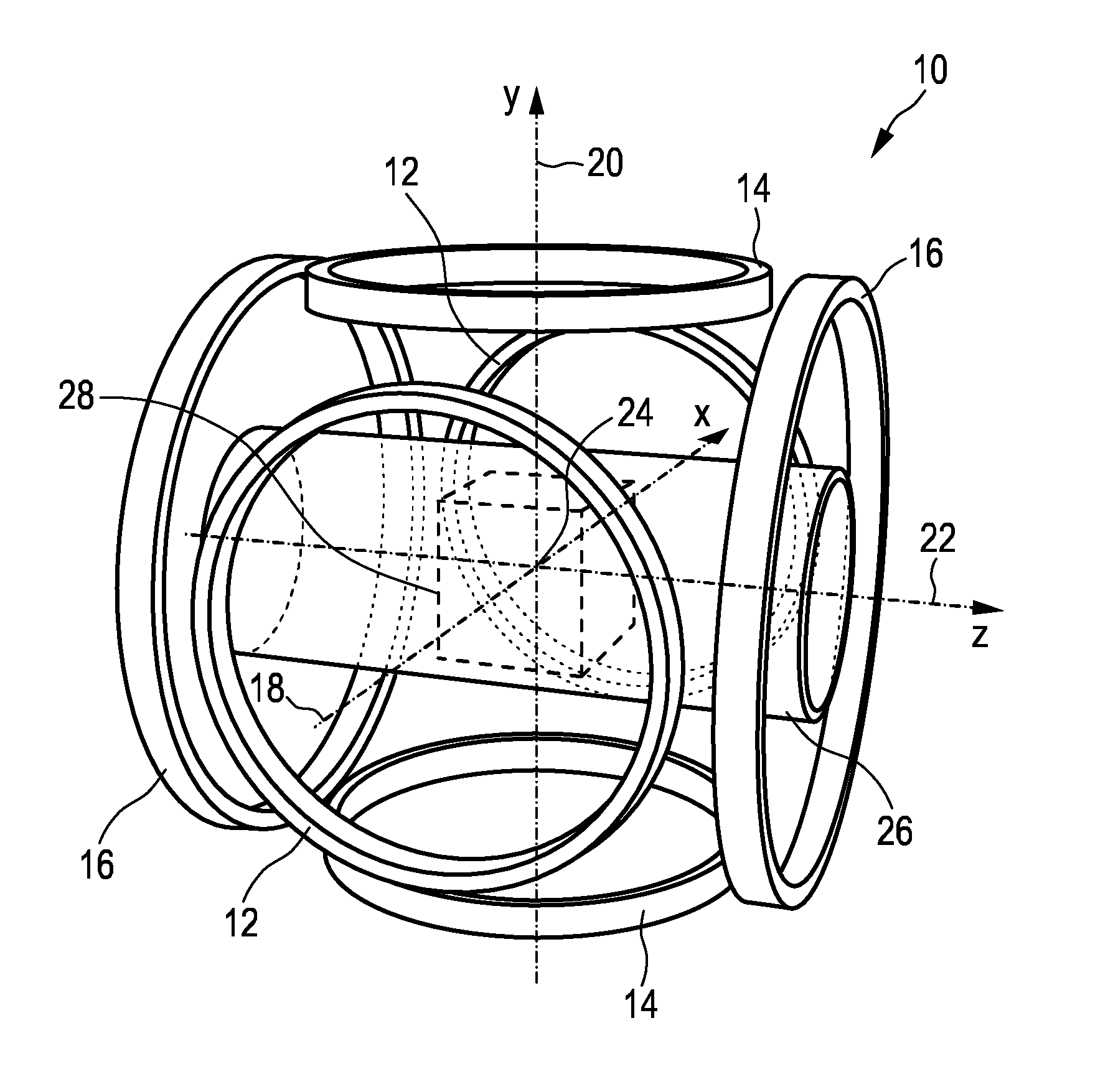
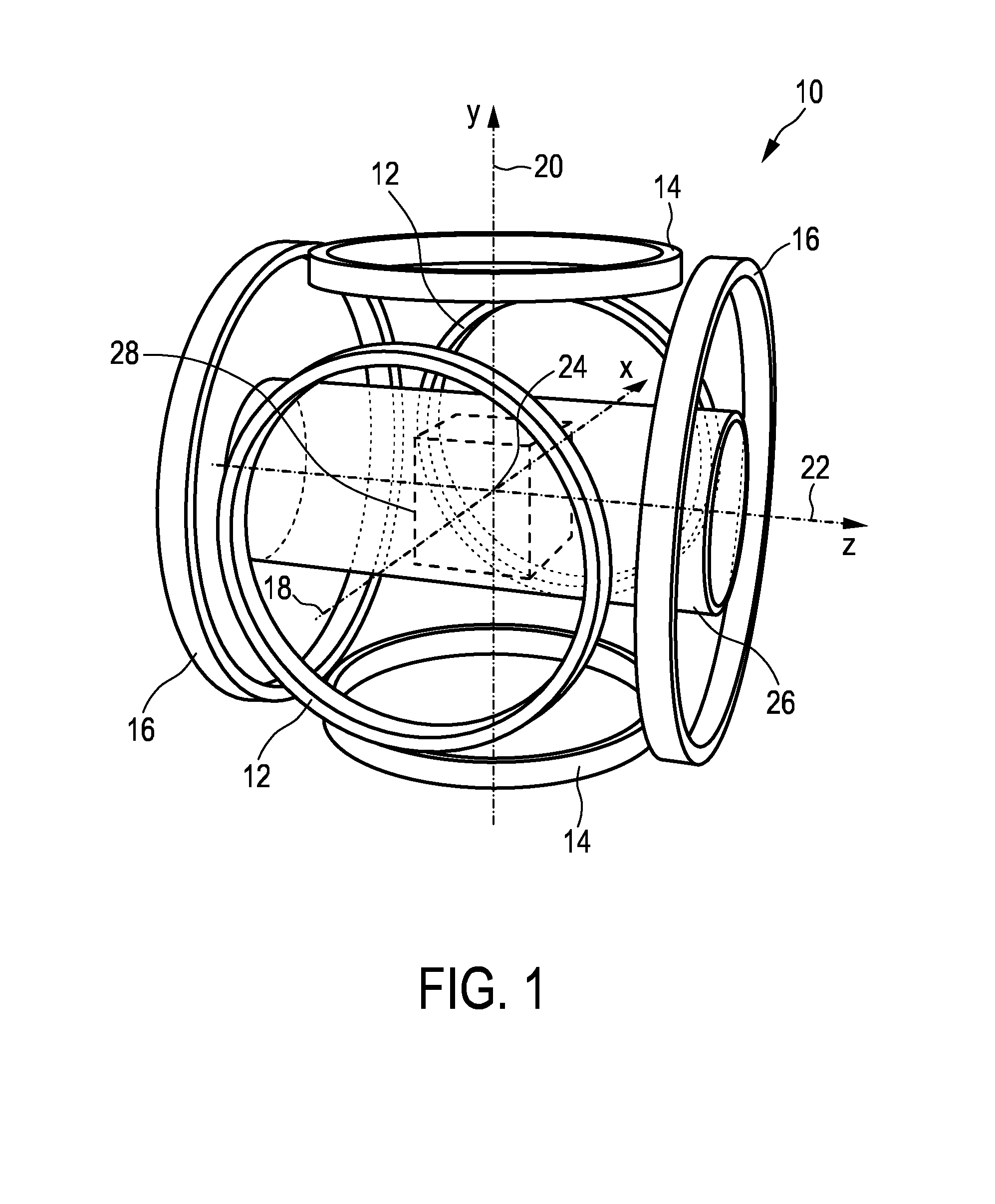
[0095]The first embodiment 10 of an MPI scanner shown in FIG. 1 has three pairs 12, 14, 16 of coaxial parallel circular coils, these coil pairs being arranged as illustrated in FIG. 1. These coil pairs 12, 14, 16 serve to generate the selection field as well as the drive and focus fields. The axes 18, 20, 22 of the three coil pairs 12, 14, 16 are mutually orthogonal and meet in a single point, designated the isocenter 24 of the MPI scanner 10. In addition, these axes 18, 20, 22 serve as the axes of a 3D Cartesian x-y-z coordinate system attached to the isocenter 24. The vertical axi...


PUM

PropertyMeasurementUnit
angleaaaaaaaaaa
frequencyaaaaaaaaaa
magnetizationaaaaaaaaaa

Abstract

The present invention relates to an apparatus and a method for influencing and/or detecting magnetic particles in a field of view (28), in particular for examination of human patients. The apparatus comprises i) selection-and-focus means (120) for generating a magnetic selection-and-focus field (50), wherein said at least one set of selection-and-focus field coils comprises—at least one inner selection-and-focus field coil (113, 115) being formed as a closed loop about an inner coil axis (115a), first inner selection-and-focus field coil (115)—a group of at least two outer selection-and-focus field coils (116-119) arranged at a larger distance from said inner coil axis (115a) than said at least one inner selection-and-focus field coil (113, 115) and at different angular positions, each being formed as a closed loop about an associated outer coil axis (116a-119a), and ii) drive means (120) comprising a drive field signal generator unit (122) and drive field coils (124; 125, 126, 127) for changing the position in space and/or size of the two sub-zones (52, 54) in the field of view (28) by means of a magnetic drive field so that the magnetization of the magnetic material changes locally.

Description

FIELD OF THE INVENTION[0001]The present invention relates to an apparatus and a method for influencing and / or detecting magnetic particles in a field of view. Further, the present invention relates to a coil arrangement and / or a pole shoe. The present invention relates particularly to the field of Magnetic Particle Imaging.BACKGROUND OF THE INVENTION[0002]Magnetic Particle Imaging (MPI) is an emerging medical imaging modality. The first versions of MPI were two-dimensional in that they produced two-dimensional images. Newer versions are three-dimensional (3D). A four-dimensional image of a non-static object can be created by combining a temporal sequence of 3D images to a movie, provided the object does not significantly change during the data acquisition for a single 3D image.[0003]MPI is a reconstructive imaging method, like Computed Tomography (CT) or Magnetic Resonance Imaging (MRI). Accordingly, an MP image of an object's volume of interest is generated in two steps. The first ...

Claims


Application Information

Patent Timeline
Patent Type & Authority Applications(United States)
IPC IPC(8): G01R33/02G01N27/72
CPCG01N27/72G01R33/02A61B5/0515
Inventor BONTUS, CLAASSCHMALE, INGOGLEICH, BERNHARD
Owner KONINKLJIJKE PHILIPS NV
Why Eureka
Try Eureka