
Measuring apparatus and article manufacturing method

Inactive Publication Date: 2014-10-16
CANON KK
View PDF2 Cites 9 Cited by
  • Summary
  • Abstract
  • Description
  • Claims
  • Application Information

AI Technical Summary

Benefits of technology

The invention is about a device that can measure things accurately using a special technique. The device reduces the effects of keeping track of changes in phase when using multiple wavelengths of light.

Problems solved by technology

For example, although there is a wavelength-scanning type measuring apparatus or a measuring apparatus using a plurality of fixed wavelengths, a wavelength-scanning type measuring apparatus alone generally has low measurement accuracy.
Consequently, the configuration of the apparatus becomes complicated, resulting in an increase in cost.
Furthermore, when an attempt is made to generate a synthetic wavelength having a long wavelength, a synthetic wavelength to be used is limited because it is difficult to optically disperse light having a required wavelength difference into components of different wavelengths.
Consequently, a white noise component is increased in the frequency noise to a signal at a frequency band near the heterodyne signal, resulting in an adverse effect on the measurement accuracy.
Thus, the different calculation processing method for a reference signal and a measured signal also leads to a different phase noise transfer.
Consequently, the error component which is commonly contained in both the reference signal and the measured signal cannot be canceled.

Method used


Image

  • Measuring apparatus and article manufacturing method
  • Measuring apparatus and article manufacturing method
  • Measuring apparatus and article manufacturing method

Examples


first embodiment

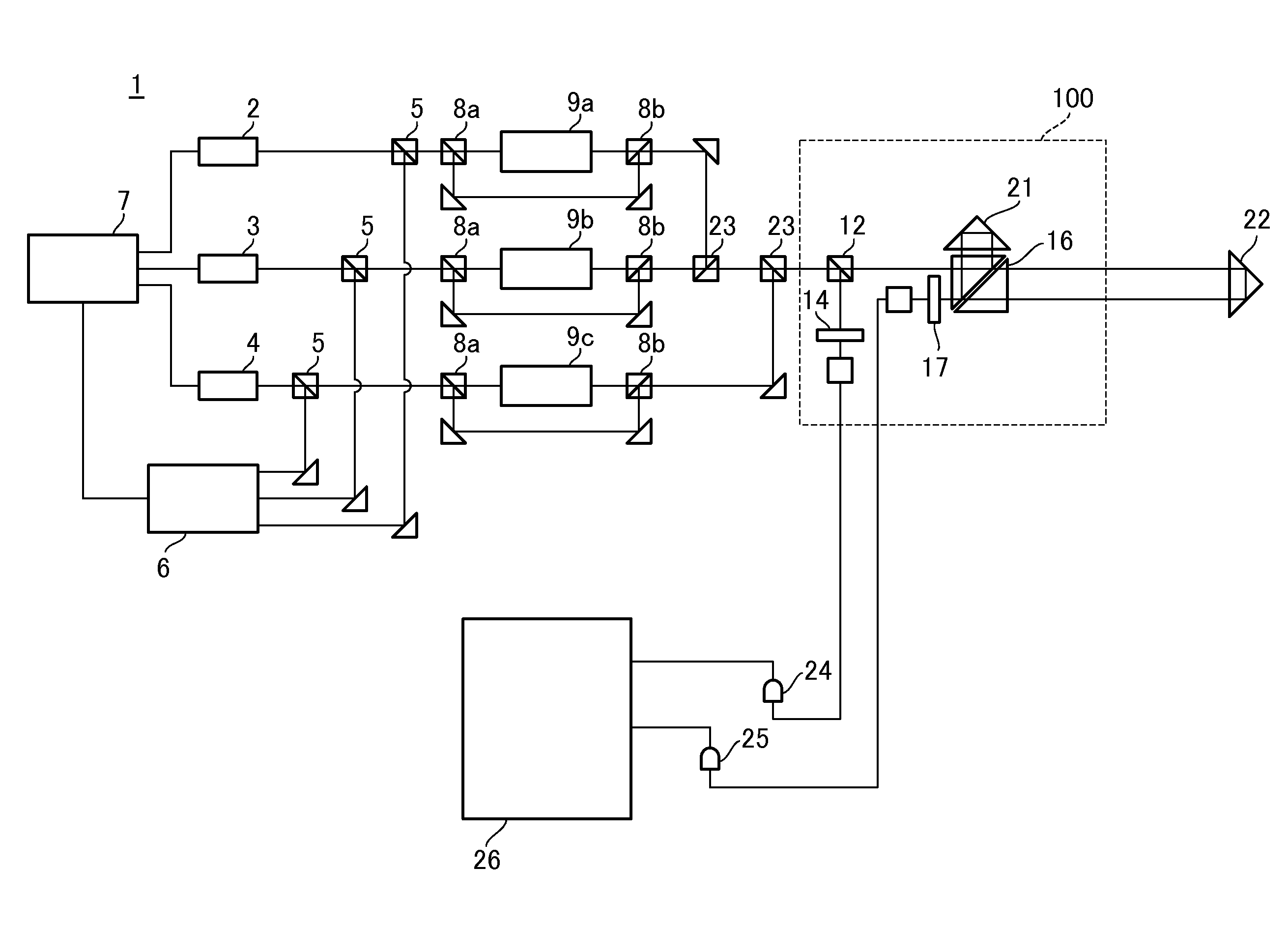
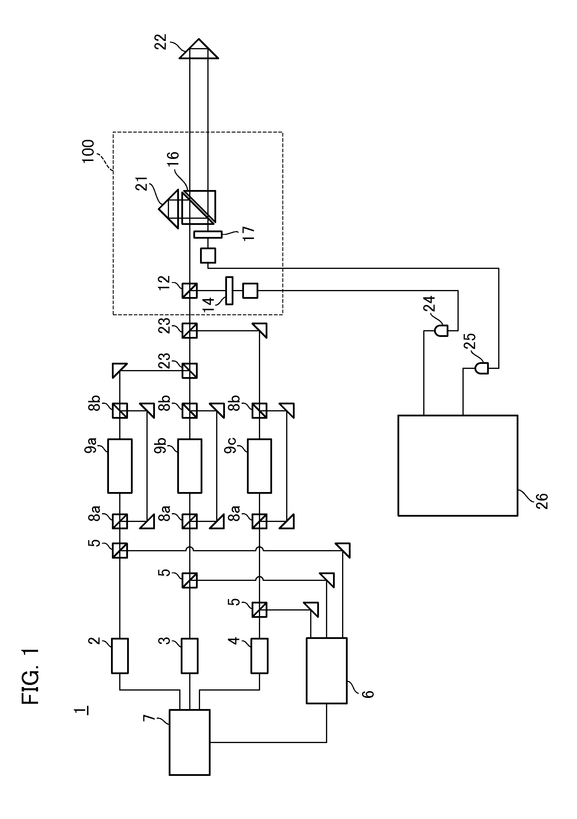
[0019]Firstly, a description will be given of a measuring apparatus according to a first embodiment of the present invention. FIG. 1 is a schematic diagram illustrating a configuration of a measuring apparatus 1 according to the present embodiment. The measuring apparatus 1 measures the position (the distance to a surface to be detected) of an object (object to be measured) 22 using a multi-wavelength heterodyne interferometer which uses light from a plurality of light sources whose wavelengths are different from each other (i.e. first light having a first wavelength, second light having a second wavelength different from the first wavelength, and so on). In the present embodiment, the number of light sources to be used, i.e., the number of wavelengths used, is three as an example. Firstly, the measuring apparatus 1 has a first light source 2, a second light source 3, and a third light source 4. The first light source 2 emits a laser beam (a light) having a first wavelength. The sec...

second embodiment

[0045]Next, a description will be given of a measuring apparatus according to a second embodiment of the present invention. In the first embodiment, a description has been given by taking an example of a measuring apparatus that measures the distance to a surface to be detected of an object 22, using a multi-wavelength heterodyne interferometer using light having three different wavelengths. In contrast, a feature of the measuring apparatus of the present embodiment lies in the fact that the measuring apparatus measures the shape of a surface to be detected on an object, using a multi-wavelength heterodyne interferometer using light having a plurality (e.g., two) of different wavelengths, by applying the aforementioned calculation processing performed by the measuring apparatus 1 of the first embodiment.

[0046]FIG. 5 is a schematic diagram illustrating a configuration of a measuring apparatus 70 according to the present embodiment. In the measuring apparatus 70 shown in FIG. 5, the s...


PUM


Abstract

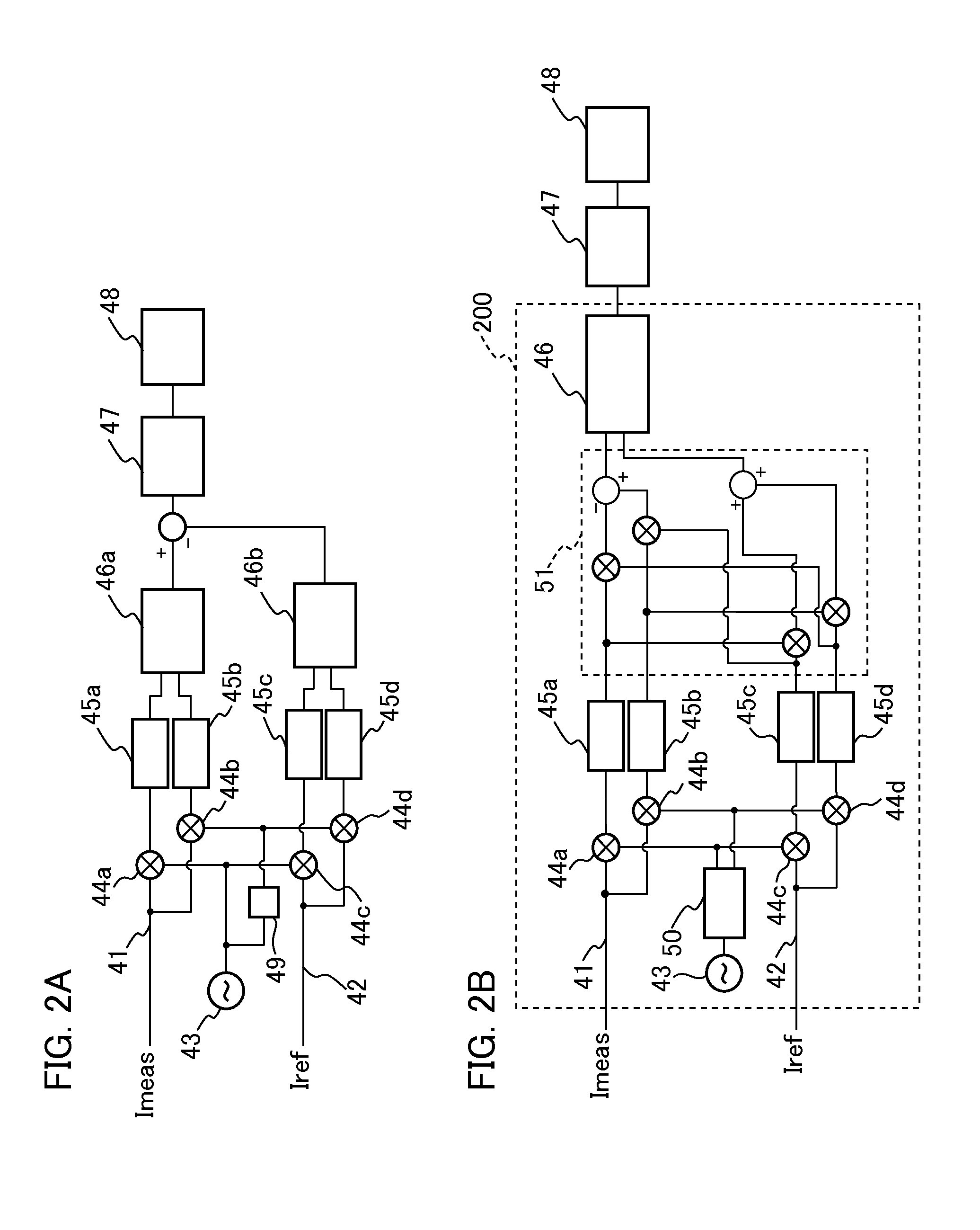
Provided is a measuring apparatus that includes a heterodyne interferometer; a first detector configured to detect interference light between reference light and light to be detected, and output a measured signal; a second detector configured to detect interference light between the first and the second light, and output a reference signal; an oscillator configured to generate a standard signal having a frequency corresponding to a frequency shift amount; a first synchronization detector configured to perform synchronous detection of the measured signal and the standard signal; a second synchronization detector configured to perform synchronous detection of the reference signal and the standard signal; a first processing unit that determines a phase difference between the measured signal and the reference signal based on the outputs of the first synchronization detector and the second synchronization detector; and a second processing unit that determines the position of the object based on the phase difference.

Description

BACKGROUND OF THE INVENTION[0001]1. Field of the Invention[0002]The present invention relates to a measuring apparatus and an article manufacturing method.[0003]2. Description of the Related Art[0004]Conventionally, there has been known a measuring apparatus using a multi-wavelength heterodyne interferometer as an apparatus for measuring the position (absolute distance to a surface to be detected) of an object or the shape of an object with high accuracy. For example, although there is a wavelength-scanning type measuring apparatus or a measuring apparatus using a plurality of fixed wavelengths, a wavelength-scanning type measuring apparatus alone generally has low measurement accuracy. Accordingly, Japanese Patent Laid-Open No. 2011-90756 discloses a wavelength-scanning type measuring apparatus that combines a relative distance measurement by a fixed wavelength with the conventional measurement so as to improve measurement accuracy. However, such a measuring apparatus optically dis...

Claims


Application Information

Patent Timeline
IPC IPC(8): G01B9/02
CPCG01B9/02083G01B9/02002G01B9/02003G01B9/02007G01B9/02075G01B2290/60
Inventor HATADA, AKIHIRO
Owner CANON KK
Learn More