Method and apparatus for ash cooling
Inactive Publication Date: 2014-10-23
SYNTHESIS ENERGY SYST
8 Cites 4 Cited by
AI-Extracted Technical Summary
Problems solved by technology
As discussed above, handling high temperature, high pressure flowing solids is not only costly but also not reliable.
Some attempts have been made to make imp...
Benefits of technology
[0010]As discussed above, handling high temperature, high pressure flowing solids is not only costly but also not reliable. Some attempts have been made to make improvement, but the results have not been satisfactory. Additionally, these improved ...
Abstract
Systems and methods for step-wise cooling high pressure and high temperature ash discharged from the gasifier used for gasification of carboneous materials, wherein a high pressure cooler cools the ash under the operating pressure of the gasifier, which may be followed by a depressurizer which brings the cooled ash to safe-handling temperature. A low temperature ash cooler may also be optionally used. Also provided is a system where a wet scrubber is used to clean the syngas from the gasifier, the waste water blow down from the scrubber is used to cool the hot ash either in the high temperature ash cooler, or the low temperature ash cooler. Steam generated in the ash coolers is supplied back to the gasifier to reduce steam consumption.
Application Domain
Muffle furnacesRetorts +3
Technology Topic
SyngasProcess engineering +6
Image
Examples
- Experimental program(1)
Example
[0040]A fluidized bed gasifier, as shown in FIG. 3, comprises a vessel housing a headspace 2 above a fluidized bed 1 of the solid material being gasified and a conical perforated gas distribution grid 7 below the bed through which the gasifying medium is introduced at sufficient velocity to fluidize the solid feed material in the gasifier. The gasifying medium (steam and/or oxygen) is introduced into the gasifier from the plenum space 4 through the grid 7 to fluidize and partially oxidize the solid feed stock.
[0041]A passage such as a pipe 6 (“center jet pipe”) in the center region at the bottom of the grid cone introduces oxidant with diluting gas to the bed. Gas velocity of the centre jet pipe 6 is normally greater than the average superficial velocity of gas in the fluidized bed 1. An ash discharge device 5 comprising an annular passage is provided around this center jet pipe 6 for coal ash agglomerated withdrawal and also for provision of additional gas, such as steam, which may serve to cool and protect the center jet pipe 6. The ash discharge device 5 is often configured to comprise a venture 3 device for sorting the ash particles at the upside of the passage. A classifier 8 can be intergraded with the ash discharge device 5. A gas stream, such as steam, moving upwards through the classifier, is often used to separate the ash particles, re-entraining those lighter and/or smaller particles whose carbon content is not yet depleted and returning them back into the reaction region,
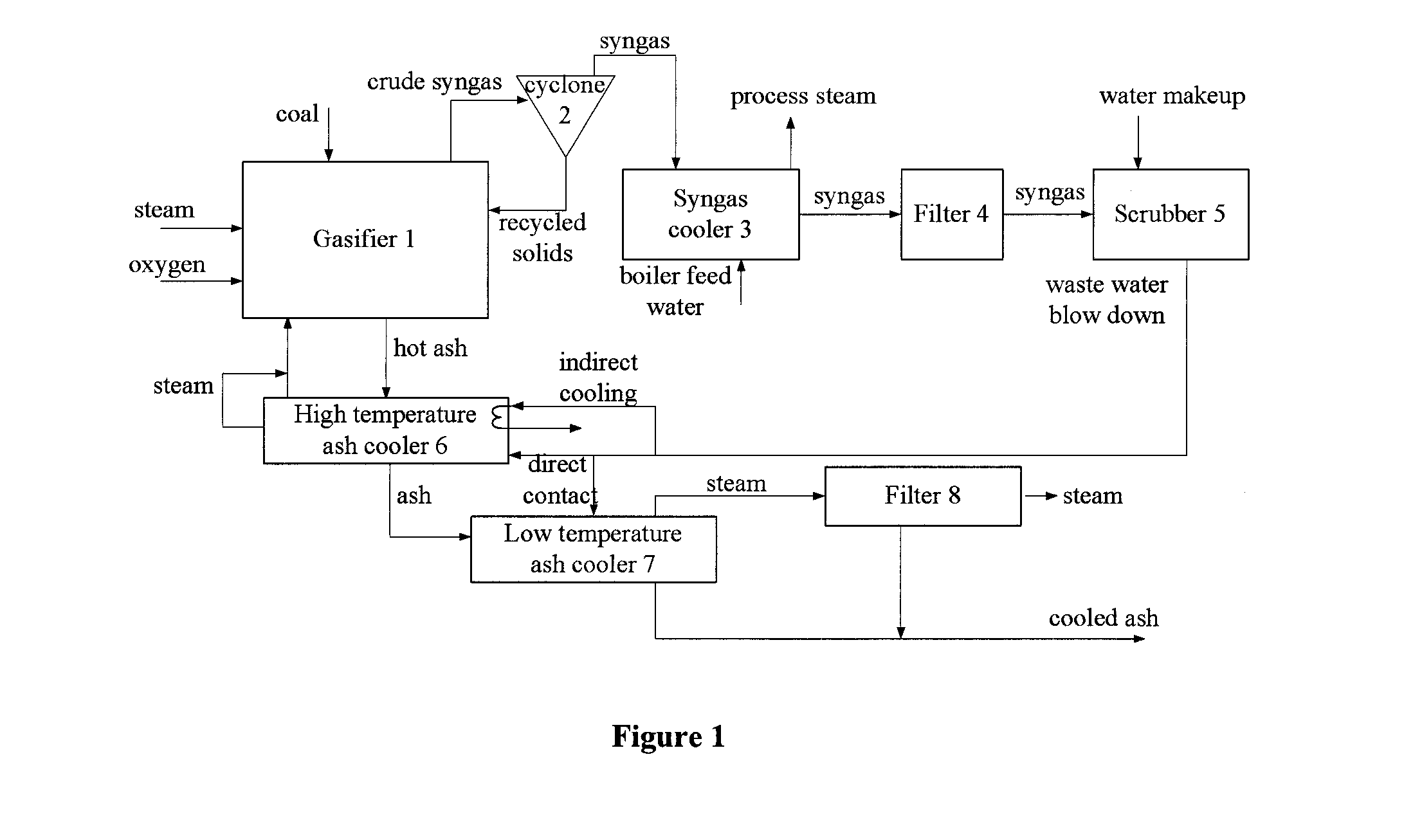
[0042]As indicated above, handling of hot ash from the ash discharge device 5 under high temperature as well as high pressure has been technically challenging in the coal gasification field. The present invention provides methods and related systems whereby the ash cooling process is separated into respective steps and the first step is a first cooling step under high pressure at high temperature. As shown in FIG. 1, the first cooling step under high pressure may be by indirect heat transfer of ash with using indirect cooling medium or by direct contacting using direct evaporative cooling liquid. After the first cooling step processed by the high temperature ash cooler (also referred as “high pressure ash cooler”), the temperature of the ash is low enough for the use of conventional equipment. Therefore, further steps such as a depressurization step can be handled at low or medium temperature with equipments of lower cost, thus the investment of equipments is reduced and the reliability of all of the remaining ash handling equipment is also increased.
[0043]In some embodiment, as shown in FIG. 2 , if a depressurization step is further performed, after depressurizing, the cooled and depressurized ash can then be cooled further in a low temperate ash cooler 7 and handled using conventional methods. The stepwise system of the present invention recovers heat from said ash in such a manner as to raise the overall efficiency of the gasification process.
[0044]A feature of the present inventive process is to first cool the ash exiting the gasifier in a high temperature cooler 6 at the gasifier pressure. The temperature of the ash after this high pressure ash cooling step may be determined based on two criteria. First the temperature is high enough such that any steam generated from the high temperature ash cooling has sufficient pressure and can be used to replace part of the fluidizing and reacting steam needed for the gasifier. Second, the temperature of the ash is low enough to allow use of conventional carbon steel equipment, such as vessels, valves, pipes, and conveyors, for the subsequent ash handling. This lowers the cost and increases the reliability of all of the remaining ash handling equipments, particularly the equipment used to remove the ash from a high pressure environment to ambient pressure.
[0045]Although above two criteria are provided, it is understood so long as at least one of two criteria are satisfied after this high pressure ash cooling step, the overall efficiency or reliability of the gasification system can be improved. Also those skilled in the art can understand that control the operating conditions in the ash coolers, such as the introduction of cooling liquid or medium, by techniques in the prior art, e.g. valves, and other device for the adjustment etc., to control the ash temperature after the high pressure ash cooling step.
[0046]The gasification process requires a large amount of steam referred as process steam which is either be generated independently or by cooling the syngas produced in the gasifier such as in a syngas cooler 3, as shown in FIG. 1, in the prior art, which is imposing a net energy penalty on the system. In comparison, in some embodiment of this present invention, the steam generated in the high temperature ash cooler can be used as port of the process steam, thereby allowing more steam to be exported from the gasification process, or reducing the need of independent steam generation. Thus, at least part of the energy penalty on the gasifier system is released.
[0047]In some embodiment, referring FIG. 2, after the high temperature ash cooling, the lower-temperature ash is then depressurized using lower cost higher reliability equipment, such as carbon steel lock hoppers. A low temperature ash cooling system follows, as shown as a low temperature ash cooler 7 in FIG. 2, which further cools the ash for ordinary solids handling and disposal. The stepwise process of the present invention lowers capital cost, improves reliability, and improves the overall efficiency of the gasification process.
[0048]In one aspect of the present invention, the system for gasifying a carbonaceous material comprises: 1) a gasifier into which the carbonaceous material and gas feeds are fed and gasified to produce a crude syngas product leaving the gasifier from the top and also produce high temperature ash under the operating pressure of the gasifier discharged from the bottom of the gasifier, 2) an ash cooler, as such the high temperature ash cooler, connected with the gasifier, wherein the ash cooler comprises i) a vessel to contain the ash during cooling and ii) an apparatus to cool the ash either via indirect heat transfer or direct contact cooling, and iii) a connection to deliver the steam(“vapor”) generated in step ii) back into the gasifier.
[0049]In one embodiment, the step-wise process of the present invention for cooling the high temperature and high pressure ash discharged from the gasifier comprises a first step wherein the free-flowing ash from the gasifier at the operating temperature of the gasifier is discharged, e.g. by gravity in the case of a fluidized bed gasifier, into a compartment or vessel, in which the ash is cooled. The operating temperature of the gasifier is usually a temperature just below the melting point of the ash e.g. 1200° C. The high-temperature ash cooling compartment itself may be configured as a fluid bed or as a moving bed.
[0050]In one embodiment the high temperature ash cooler may be a “direct contact” cooler wherein water or other direct evaporative cooling liquid is directly contacted with the hot ash and converted to steam, which flows countercurrent to the ash discharge into the gasifier via a channel connecting the gasifier to the high temperature ash cooler. In this way, the heat energy contained in the ash is used to generate steam which is used directly in the gasification reactor.
[0051]Direct contact may be affected by many methods well-known to those skilled in the art. For example, water, preferably atomized, may be injected into the hot ash so long as the flow-ability of the ash is maintained. This may be done via a water supply apparatus which comprises means to disperse the water into the ash such as spray nozzles, atomizing spray nozzles, microporous pipes, which for example may be made from sintered metal powder or fibers, pipes or other flow channels with drilled holes. This direct contact cooling step can be achieved in either a moving bed or fluid bed ash cooler.
[0052]Indirect cooling can be used in combination with or instead of direct contact cooling. Whether this is means of jacketing of the vessel, cooling coils, or cooling panels or any other common means of indirect heat transfer, a indirect cooling medium is heated or evaporated in a flow channel separated from the ash. Steam is generated in the flow channel and is relatively clean compared to the steam generated via direct contact. Preferably, the steam is at a pressure higher than that of the gasifier and can be used in the gasifier or for other uses.
[0053]After the high temperature cooler, the ash reaches a temperature at which any further handling or processing can be accomplished using e.g. ordinary carbon steel materials, which function well and reliably at a temperature below 500° C., preferably below 350° C. In one embodiment, after the high temperature ash cooler, the ash may be reduced in pressure, e.g. in a depressurizer, to ambient pressure for any further handling or cooling. This can be achieved by a variety of means, such as via valves and lock-hoppers well-known to those skilled in the art. These are conventional equipment and can operate rather reliably at a temperature of 300-550° C. even under the operating pressure of the gasifier.
[0054]A lock hopper is a well-known depressurizing device, and generally comprises a vessel into and out of which the ash flows by gravity, with valves at the top and bottom that seal against pressure and solids flow, and means to pressurize and depressurize the vessel, and associated valves and controls to regulate the gas flow.
[0055]The cooled and depressurized ash may optionally undergo a further cooling step using a second cooler, or a low temperature ash cooler, for ease of handling or safe disposal, e.g. to not more than 140° C. for handling via belt conveyors. Any commonly available low pressure solids cooler, including a direct contact or indirect heat transfer cooler, e.g. a screw cooler, can be used as the low temperature ash cooler.
[0056]In the low temperature ash cooling step after depressurization, a scrubber blowdown (described below in detail) may be used in direct contact with the ash to provide cooling, transfer salts and suspended solids to the ash, and further recover water without salt for reuse, thus lowering wastewater treatment and reducing overall water consumption.
[0057]In some embodiment, a two-step cooling process (i.e. a high pressure cooling followed by depressurizing) of the present invention thus allows the overall cost of an ash cooling and depressurization system to be lowered, its reliability increased, and the bulk of the heat available in the ash, which is the heat of the ash from gasifier operating temperature to the exit temperature of the high temperature ash cooler, is directly converted to process steam. As mentioned above, the process steam converted has the highest value possible for a gasifier system, for use in the gasifier without any addition steam handling.
[0058]In one embodiment, the high temperature cooler may also be designed to cool the ash to a lower temperature such that a low temperature ash cooler is not needed. Such a process may be desired if high process efficiency is needed, especially when the gasifier feed has high ash content. Such a lower temperature may be achievable even with direct contact cooling, so long as the water saturation pressure at the exit temperature of the high temperature ash cooler is above the gasifier operating pressure.
[0059]In one embodiment, the high temperature cooler may also be designed to cool the ash to a lower temperature and the cooled ash is cooled by a low temperature ash cooler. In this embodiment, the depressurizer is not needed. Such a process may be desired when the pressure of the cooled ash is needed.
[0060]The above mentioned and other features of this invention and the manner of obtaining and using them will become more apparent, and will be best understood, by reference to the following drawing and description.
[0061]Referring to FIG. 1, hot ash passes from the gasifier 1 into the ash cooling apparatus. Depending on the operating conditions of the gasifier 1, the hot ash may be at a temperature from 500° to 1200° C. at the discharge point from the gasifier 1. The temperature of the ash leaving the ash cooling device is determined by the operating pressure of the gasifier. As long as the saturation pressure of water at the ash exit temperature is above the gasifier operating pressure, water can be injected directly into the moving or fluid ash.
[0062]The “pre-determined threshold temperature” may be determined by the following two factors. Firstly, in order to keep the flowability of the ash, liquid water should be avoided in the ash cooler. Thus, the temperature of the cooled ash (T1) should be kept at least above the boiling point of water at the ash cooling pressure. Preferably, the temperature is at or above the critical temperature of water (i.e. 374° C.). Secondly, since the steam generated flows into the gasifier (more detail below), the pressure of the steam should be above the pressure of the points at which the steam is introduced into the gasifier. Thus, the temperature of the cooled ash (T2) should be high enough. Therefore, the pre-determined threshold temperature should not be lower than either T1 or T2.
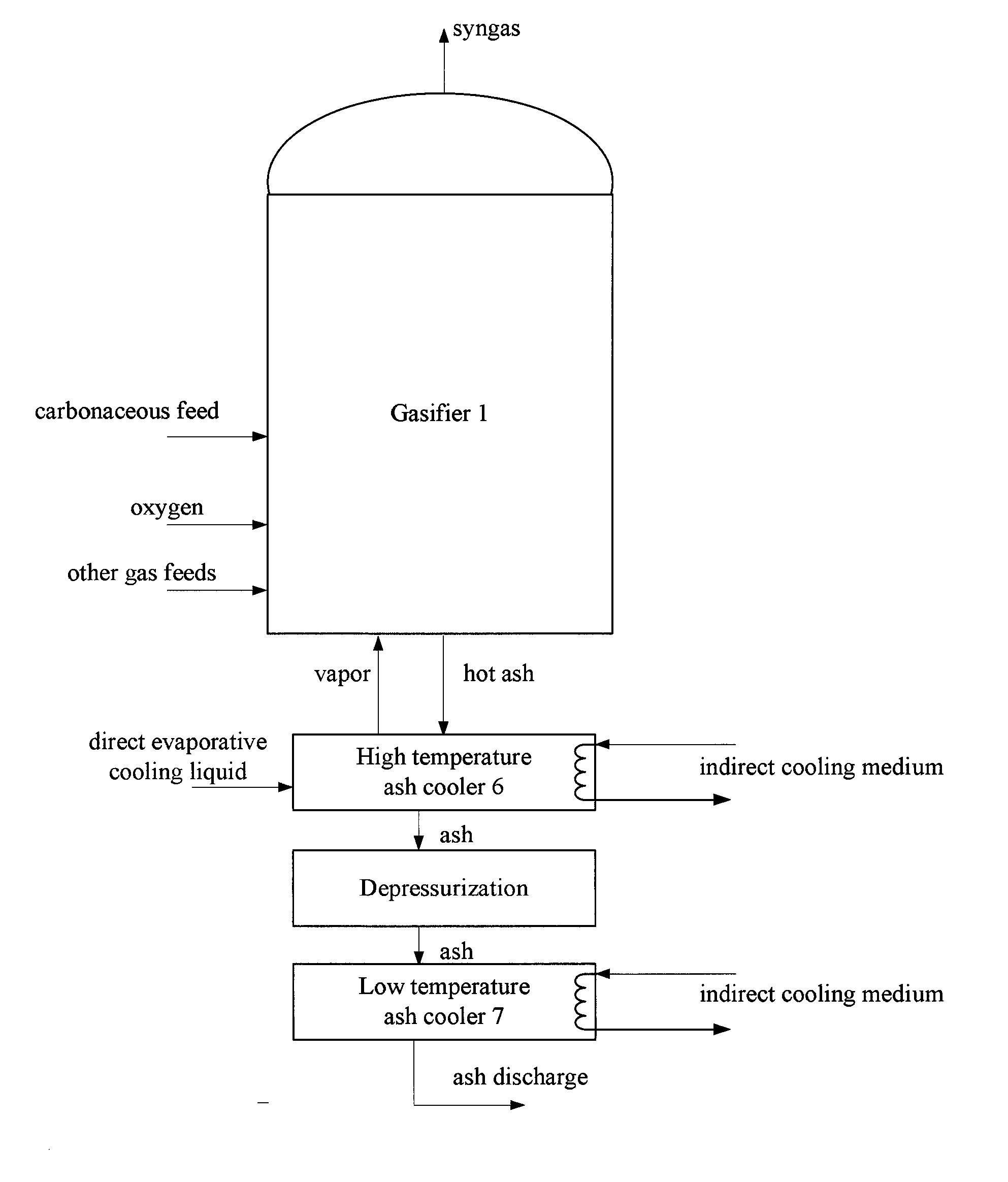
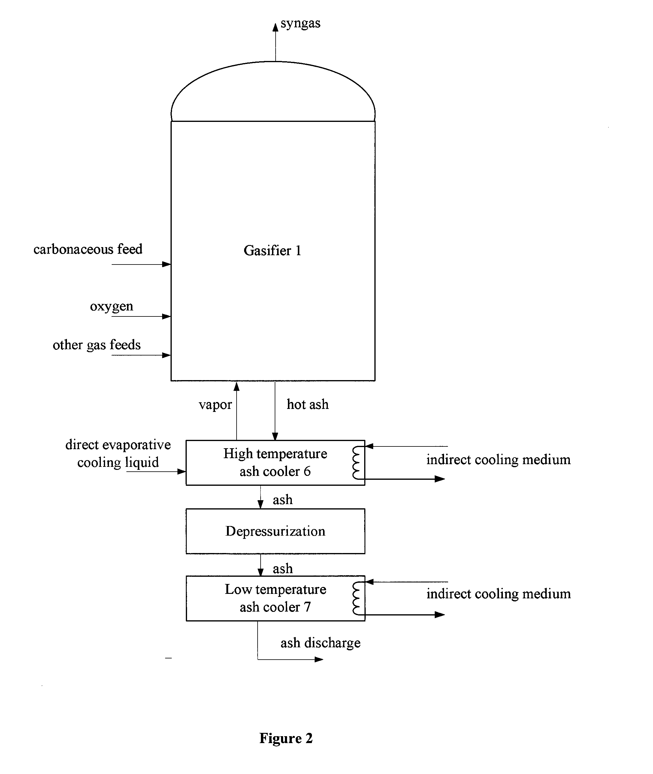
[0063]In a preferred embodiment of the invention, the rate and amount of water is controlled so that it is dispersed and mixes with the hot solids properly, and completely evaporates without affecting the flowability of the ash. The steam thus generated moves up into the reacting zone of gasifier.
[0064]The flow of the cooling water can controlled by a flow control device such as a control valve where the flow of the water is controlled by temperature or pressure measurement in the ash cooler to regulate to the amount of cooling desired.
[0065]In this manner, the thermal energy contained in the hot ash is used to generate steam needed for the gasification reaction, thus displacing the amount of clean, high pressure steam otherwise needed in the gasification reaction and typically generated in a separate boiler. It should be noted that the steam generated by direct contact with the ash is a “dirty” steam containing a variety of contaminants, making it unsuitable for most other purposes, but suitable for use in the gasification process.
[0066]The steam generated by direct or indirect contact can be introduced in the gasifier through various points of the gasifier. As shown in FIG. 3, the steam can flow into the plenum space 4 via a channel and then be introduced in the gasifier through the grid 7, or be introduced into the center jet pipe 6 as part of the jet gas, or through the classifier 8 integrated with the ash discharge device 5. Since steam generated by direct contact contains ash which may cause grid plug problem for the grid 7, this direct contacting steam, preferably, is introduced to the classifier 8, such as through the classifier gas inlet on the classifier 8.
[0067]For example, in a SES gasifier (U.S. Ser. No. 13/532,769), if a 10 wt % ash feed stock is used, and the exit ash temperature is 1000° C., and is cooled to 400° C. Almost 1 kg of steam can be generated using the present invention for each 7 kg of ash which accounts for an appreciable fraction of the total gasification steam required.
[0068]Referring to FIG. 2, which illustrates the sequential arrangement of steps of one embodiment of the present process, the ash is first cooled to reach a temperature typically in the region of 300 to 550° C. in a vessel of the high temperature ash cooler 6 at a pressure close to the gasifier pressure. The ash is then depressurized to ambient pressure via equipment such as lock-hoppers. Regardless of the depressurizing method used, for safety and maintenance purposes, some form of isolation valve may be required between the high pressure region and the low pressure region and this valve is far less expensive and more reliable at the exit temperature of the high temperature ash cooler than a valve specified for service at temperatures (800 to 900° C.) near the gasifier temperature (typically 1000° C. for the SES gasifier). Once the ash is at atmospheric pressure, it can be further cooled in a low temperature ash cooler 7 to safe handling temperatures, typically 50 to 140° C., in any number of manners using readily available solids cooling equipment.
[0069]Accordingly another aspect of the present invention, in another embodiment, the invention further provides a method and system of coal gasification wherein at least a part of wastewater stream generated from one or more of the gas cleaning steps (e.g. the scrubber blowdown water) is recycled and applied to the hot ash residue from the gasification process, in such a manner that the salts and suspended solids in the waste water remain with the ash, wherein steam is generated in the process, which steam may be used for several purposes such as being fed back to the gasification process. The amount of water sent to wastewater treatment of the system is reduced.
[0070]In one embodiment, the invention provides a system for gasifying a carbonaceous material, referring to FIG. 1, wherein the system comprises:
[0071]1) a gasifier 1 into which the carbonaceous material such as coal is fed and gasified to produce a crude syngas containing gaseous and particulate pollutants;
[0072]2) optionally, at least one device to remove a portion of the particulate pollutants and recycle the solids in the crude syngas such as cyclone 2, cool the crude syngas such as syngas cooler 3;
[0073]3) optionally, another device to further remove solids from the gas stream, such as filter 4 as shown in FIG. 1;
[0074]4) a scrubber 5, wherein the cooled and partially cleaned syngas is further cleaned to produce a waste water stream;
[0075]5) at least one ash cooler connected with the gasifier to receive hot ash under pressure from the gasifier, such as the high temperature ash cooler 6;
[0076]6) a connection to deliver at least a portion of the waste water stream to the ash cooler, wherein all or part of the waste water stream is converted into steam; and
[0077]7) a connection to deliver the steam generated in the ash cooler back into the gasifier.
[0078]According to an embodiment of the present invention, the waste water stream from the scrubber can be delivered to either or both of the high temperature ash cooler or low temperature ash cooler. Because the ash temperature is much higher than the boiling point of water in either of the ash coolers, the water in the waste water stream, along with other volatile components will evaporate, to generate a supply of steam, while leaving the particulate pollutants and other non-volatile components behind with the ash particles. The supply of steam from the high temperature ash cooler is directed to the gasifier and supplements the steam supply needed for the gasification process. Steam generated from the wastewater used in the low temperature ash cooler may be condensed in use as a low temperature heat source or the condensate used as process water makeup.
[0079]In one embodiment, this invention deals with the recycle of waste water emanating from a water scrubber used for removing solids from product syngas from e.g. a fluidized bed coal gasification process. Typically, a water scrubber follows the cyclones and filters (e.g. bag house filters or candle filters) used to remove solids from the gas. This scrubber captures most, or nearly all, of the halide, ammonia, cyanides, remaining particulate matter not removed in the cyclones and filters, and some trace gas species that are at least partially water soluble.
[0080]Scrubbers, or wet scrubbers suitable for the present invention, are common and well-known devices that use liquid to wash and remove unwanted particulate and/or gas pollutants from a gas stream. There are a diverse group of such devices that can be used. Scrubbers are one of the primary devices that control gaseous emissions, especially acid gases. Scrubbers can also be used for heat recovery from hot gases by flue-gas condensation. Wet scrubbing works via the contact of target compounds or particulate matter with the scrubbing solution, which may simply be water. Water soluble toxic and/or corrosive gases like HCl, H2S, SO2 or ammonia (NH3) can be removed very well by a wet scrubber. The water spray may also condense certain condensables such as tar and oil. Removal efficiency of pollutants is improved by increasing residence time in the scrubber or by the increase of surface area of the scrubber solution by e.g. spraying.
[0081]According to one embodiment of the present invention, a portion (which includes all or none) of the waste water stream from the scrubber which contains the removed contaminants may be applied directly to contact with hot gasifier ash at the gasifier operating pressure which is typically, but not restricted to, 10 to 60 bar. Alternatively, the waste water stream may be applied in indirect heat transfer against the hot ash, and substantially evaporated. In either case, the steam generated from the cooling or the hot ash and any contaminants in the wastewater stream that evaporate with the steam, can be re-introduced into the gasifier as part of the required steam for gasification purposes, reducing the overall water requirements for the gasification plant.
[0082]In another embodiment, a portion or all of the wastewater stream can be applied to the ash directly in a low pressure ash cooling step. In this case, some of the water may be used to partially hydrate the ash for dust control in handling, for example raising the hot ash water content from essentially zero to 5 wt %. Some of the water evaporates and this steam may also be as a low temperature heat source with the condensate reused as process water, be vented, be sent to a flare, or condensed and reused as process water after removal of any entrained ash.
[0083]In another embodiment, the method of the present invention places the salts and suspended solids from the wastewater into the ash product from the gasifier, reduces plant water consumption, and wholly or in part eliminates wastewater treatment for the gasification process. The high pressure steam generated from the direct injection of waste water to the hot ash can be directly connected to the gasifier, without having been cleaned to remove any entrained ash particles, thereby reducing the need for high pressure clean steam, and resulting in significant increase in heat energy efficiency, yet only minimal increase in capital costs.
[0084]It is understood that examples and embodiments described herein are for illustrative purpose only and that various modifications or changes in light thereof will be suggested to persons skilled in the art and are to be included within the spirit and purview of this application and scope of the appended claims. All publications, patents and patent applications cited in this patent are hereby incorporated by reference for all purposes.
[0085]One or more features from any embodiment maybe combined with one or more features of any other embodiment without departing from the scope of the disclosure. The above description is illustrative and is not restrictive. Many variations of the invention will become apparent to those skilled in the art upon review of the disclosure. The scope of the invention should, therefore, be determined not with reference to the above description, but instead should be determined with reference to the claims along with their full scope or equivalents.
PUM


Description & Claims & Application Information
We can also present the details of the Description, Claims and Application information to help users get a comprehensive understanding of the technical details of the patent, such as background art, summary of invention, brief description of drawings, description of embodiments, and other original content. On the other hand, users can also determine the specific scope of protection of the technology through the list of claims; as well as understand the changes in the life cycle of the technology with the presentation of the patent timeline. Login to view more.