

Light-emitting diode illuminating apparatus
- Summary
- Abstract
- Description
- Claims
- Application Information
AI Technical Summary
Benefits of technology
Problems solved by technology
Method used
Image

Examples
Embodiment Construction
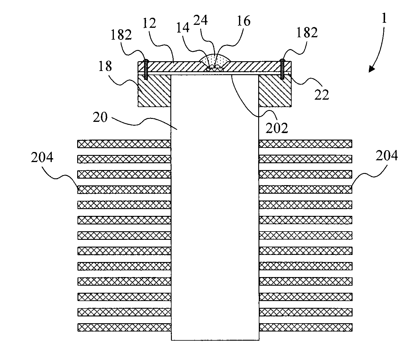
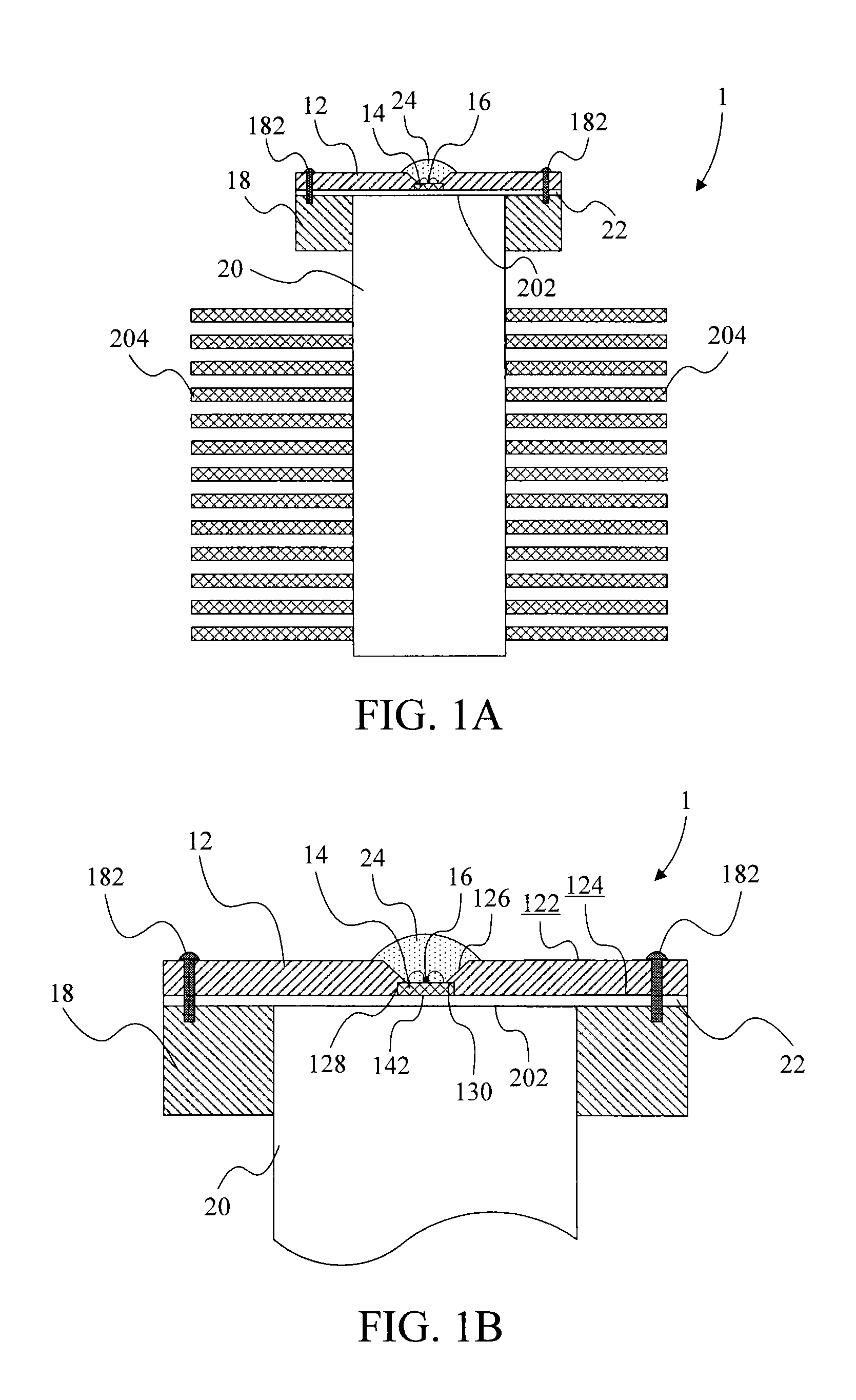
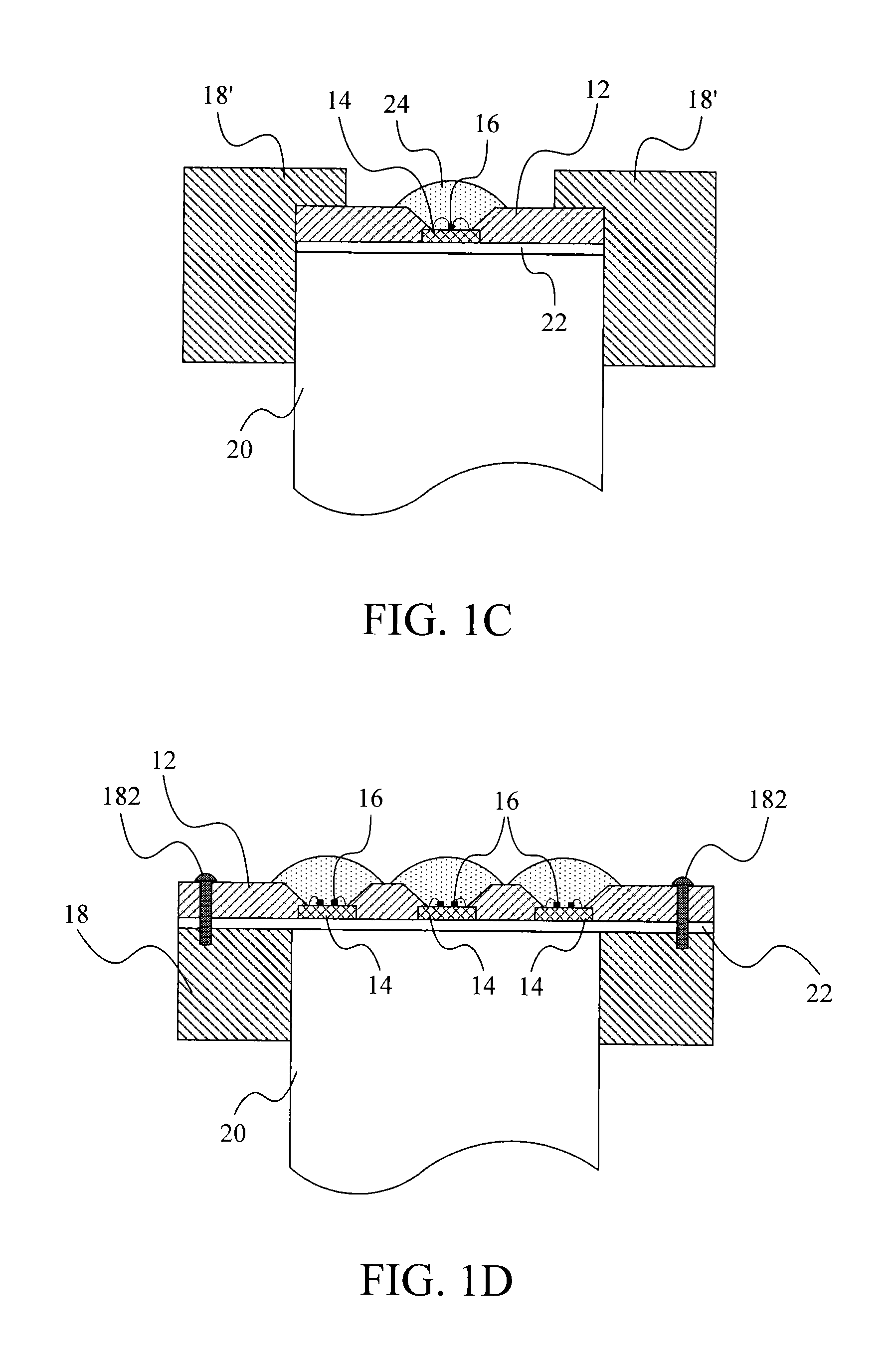
[0028]Please refer to FIGS. 1A and 1B. FIG. 1A is a cross section of a first preferred embodiment of the LED illuminating apparatus 1 of the invention. FIG. 1B is a local enlarged view of FIG. 1A. The LED illuminating apparatus 1 of the invention includes a carrier 12, a substrate 14, a first LED chip 16, a support 18, a heat-conducting device 20, and a thermal phase-change material 22.
[0029]The carrier 12 includes a top surface 122 and a bottom surface 124. A first recess 126 is formed on the top surface 122 of the carrier 12, and a second recess 128 is formed on the bottom surface 124 of the carrier 12. The first recess 126 communicates with the second recess 128. The substrate 14 is embedded into the second recess 128. The first LED chip 16 is disposed on the substrate 14. Besides, the diameter of the first recess 126 is smaller than the diameter of the second recess 128, so the second recess 128 has a top part 130. The substrate 14 is connected to the top part 130. The top part ...
PUM
 Abstract
Description
Claims
Application Information