System and methods for extracting correlation curves for an organic light emitting device
What is Al technical title?
Al technical title is built by PatSnap Al team. It summarizes the technical point description of the patent document.
a technology of organic light emitting devices and correlation curves, applied in the field of displays, can solve the problems of light output at a constant current to decrease, current to drop at a constant bias voltage, and oled devices also undergo electrical degradation
Inactive Publication Date: 2014-10-23
IGNIS INNOVATION
View PDF3 Cites 14 Cited by
Summary
Abstract
Description
Claims
Application Information
AI Technical Summary
This helps you quickly interpret patents by identifying the three key elements:
Problems solved by technology
Method used
Benefits of technology
Problems solved by technology
During operation of an organic light emitting diode device, it undergoes degradation, which causes light output at a constant current to decrease over time.
The OLED device also undergoes an electrical degradation, which causes the current to drop at a constant bias voltage over time.
These degradations are caused primarily by stress related to the magnitude and duration
Method used
Image
Click on the blue label to locate the original text in one second.
Reading with bidirectional positioning of images and text.
Examples
Embodiment Construction
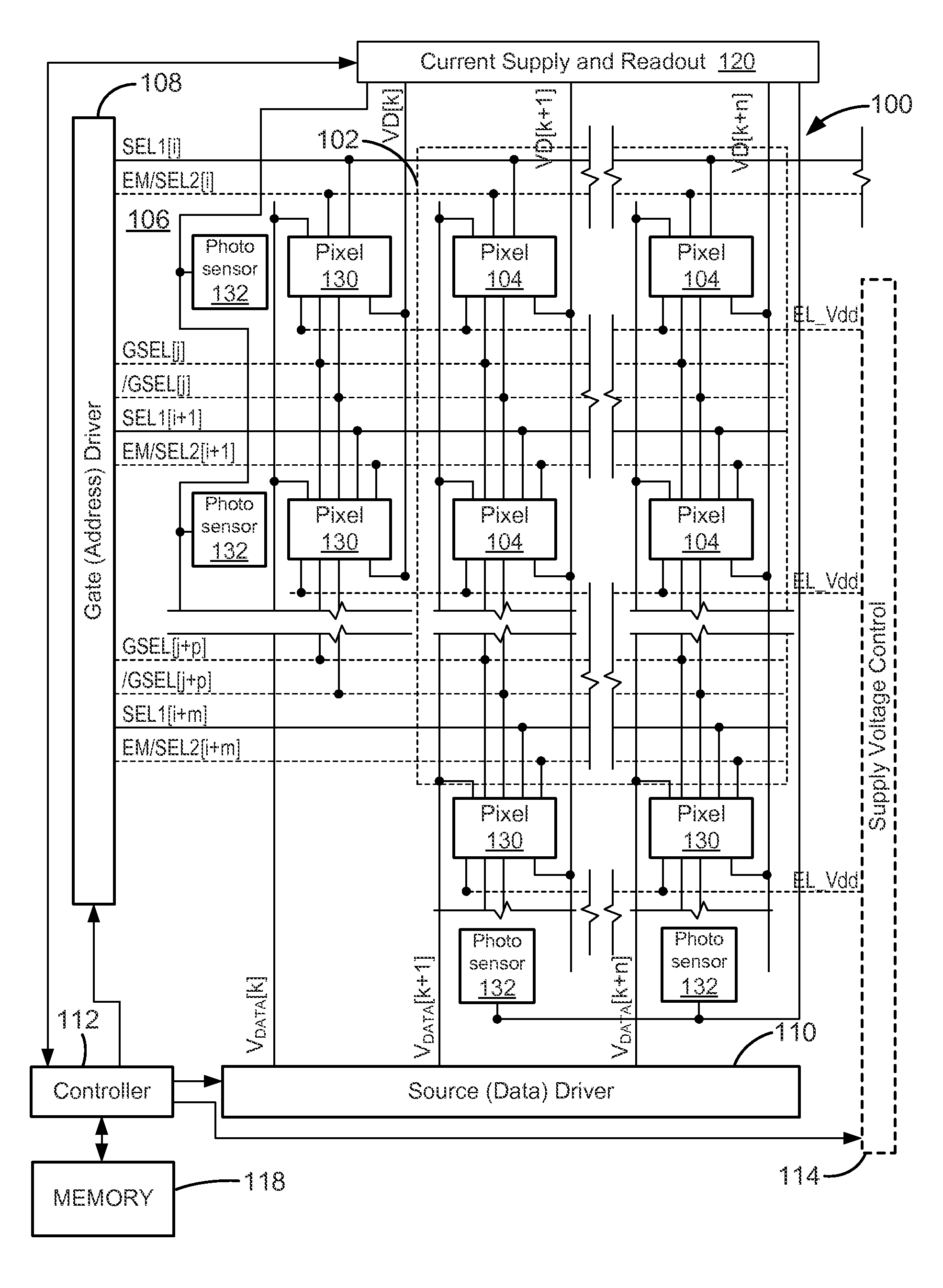
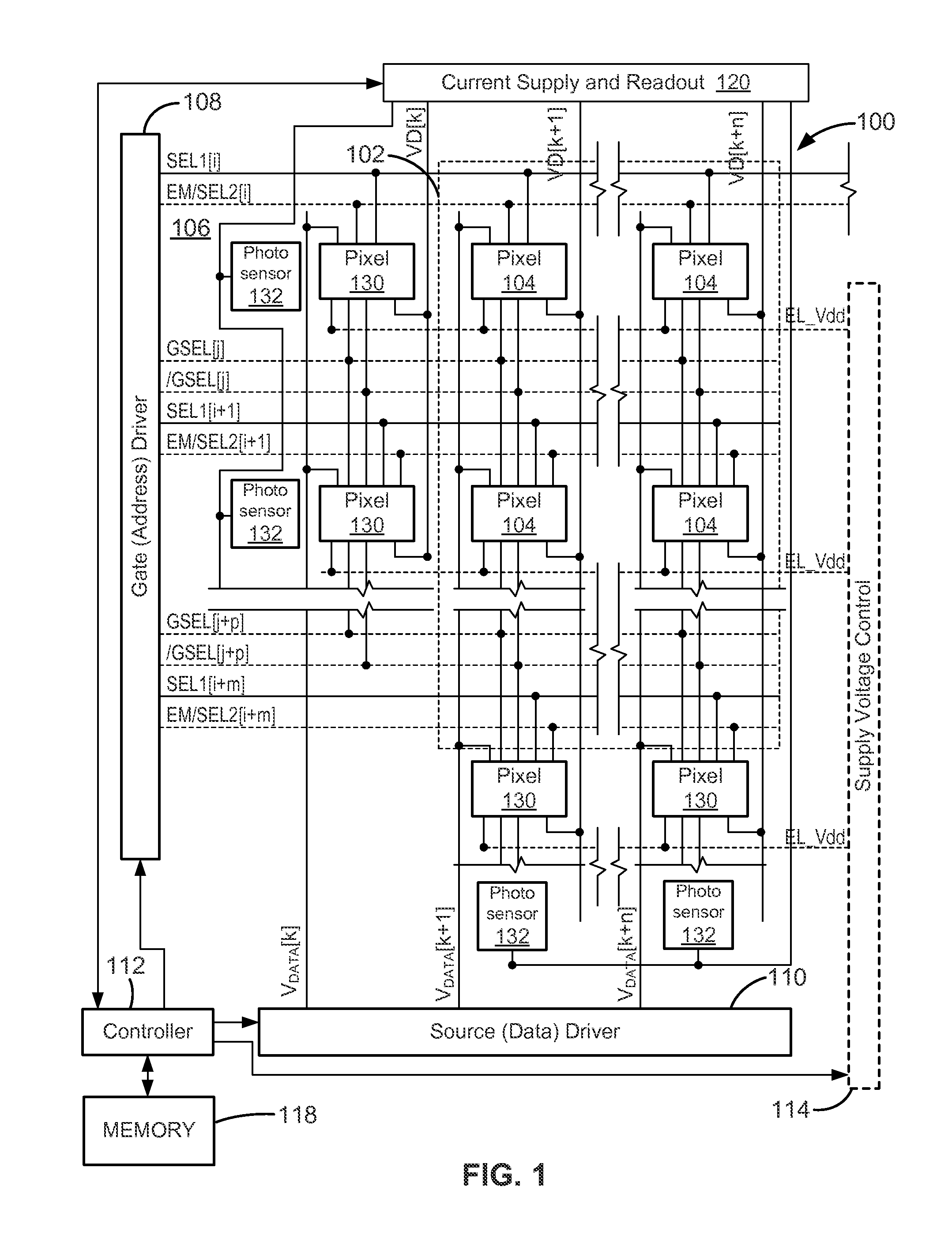
[0030]FIG. 1 is an electronic display system 100 having an active matrix area or pixel array 102 in which an array of active pixels 104 are arranged in a row and column configuration. For ease of illustration, only two rows and columns are shown. External to the active matrix area, which is the pixel array 102, is a peripheral area 106 where peripheral circuitry for driving and controlling the area of the pixel array 102 are disposed. The peripheral circuitry includes a gate or address driver circuit 108, a source or data driver circuit 110, a controller 112, and an optional supply voltage (e.g., EL_Vdd) driver 114. The controller 112 controls the gate, source, and supply voltage drivers 108, 110, 114. The gate driver 108, under control of the controller 112, operates on address or select lines SEL[i], SEL[i+1], and so forth, one for each row of pixels 104 in the pixel array 102. In pixel sharing configurations described below, the gate or address driver circuit 108 can also optiona...
PUM
Abstract
A system for compensating the input signals to arrays of pixels that include semiconductor devices that age differently under different ambient and stress conditions. The system creates a library of compensation curves for different stress conditions of the semiconductor devices; identifies the stress conditions for at least a selected one of the semiconductor devices based on the rate of change or absolute value of at least one parameter of at least the selected device; selects a compensation curve for the selected device based on the identified stress conditions; calculates compensation parameters for the selected device based on the selected compensation curve; and compensates an input signal for the selected device based on the calculated compensation parameters.
Description
CROSS-REFERENCE TO RELATED APPLICATIONS[0001]This application is a continuation-in-part of and claims priority to pending U.S. patent application Ser. No. 14 / 314,514, filed Jun. 25, 2014 [Attorney Docket No. 058161-000042USP2], which is a continuation-in-part of pending U.S. patent application Ser. No. 14 / 286,711, filed May 23, 2014 [Attorney Docket No. 058161-000042USP1], which is a continuation-in-part of U.S. patent application Ser. No. 14 / 027,811, filed Sep. 16, 2013 [Attorney Docket No. 058161-000042USC1], which is a continuation of U.S. patent application Ser. No. 13 / 020,252, filed Feb. 3, 2011, now U.S. Pat. No. 8,589,100 [Attorney Docket No. 058161-000042USPT], which claims priority to Canadian Application No. 2,692,097, filed Feb. 4, 2010, now abandoned [Attorney Docket No. 058161-000042CAPT], each of which is hereby incorporated by reference herein in its entirety.FIELD OF THE INVENTION[0002]This invention is directed generally to displays that use light emissive devices s...
Claims
Application Information
Patent Timeline
Application Date:The date an application was filed.
Publication Date:The date a patent or application was officially published.
First Publication Date:The earliest publication date of a patent with the same application number.
Issue Date:Publication date of the patent grant document.
PCT Entry Date:The Entry date of PCT National Phase.
Estimated Expiry Date:The statutory expiry date of a patent right according to the Patent Law, and it is the longest term of protection that the patent right can achieve without the termination of the patent right due to other reasons(Term extension factor has been taken into account ).
Invalid Date:Actual expiry date is based on effective date or publication date of legal transaction data of invalid patent.