Vibration control of a swashplateless coaxial rotor

a coaxial rotor and swashplate technology, applied in the field of rotary wing aircraft, can solve the problems of increasing maintenance and operating costs, contributing to crew fatigue, and periodic aerodynamic loads on the rotor blades

Active Publication Date: 2014-10-23
SIKORSKY AIRCRAFT CORP
View PDF7 Cites 23 Cited by
  • Summary
  • Abstract
  • Description
  • Claims
  • Application Information

AI Technical Summary

Benefits of technology

[0012]FIG. 3 is a schematic longitudinal sectional view of a swashplateless control system of the dual, counter-rotating, coaxial rotor system of FIG. 2;
[0013]FIG. 4 is a perspective view of an exemplary lower rotor control system according to an embodiment of the invention;
[0014]FIG. 5 is a block diagram of the forces, moments, and control loads available f

Problems solved by technology

Such vibrations may contribute to crew fatigue, increased maintenance, and operating costs.
A major cause of such vibrations is periodic aerodynamic loads on the rotor blades.
Reducing rotor-blade induced vibrations in a dual, counter-rotating, coaxial rotor system is further complicated as control i

Method used


Image

  • Vibration control of a swashplateless coaxial rotor
  • Vibration control of a swashplateless coaxial rotor
  • Vibration control of a swashplateless coaxial rotor

Examples


Embodiment Construction

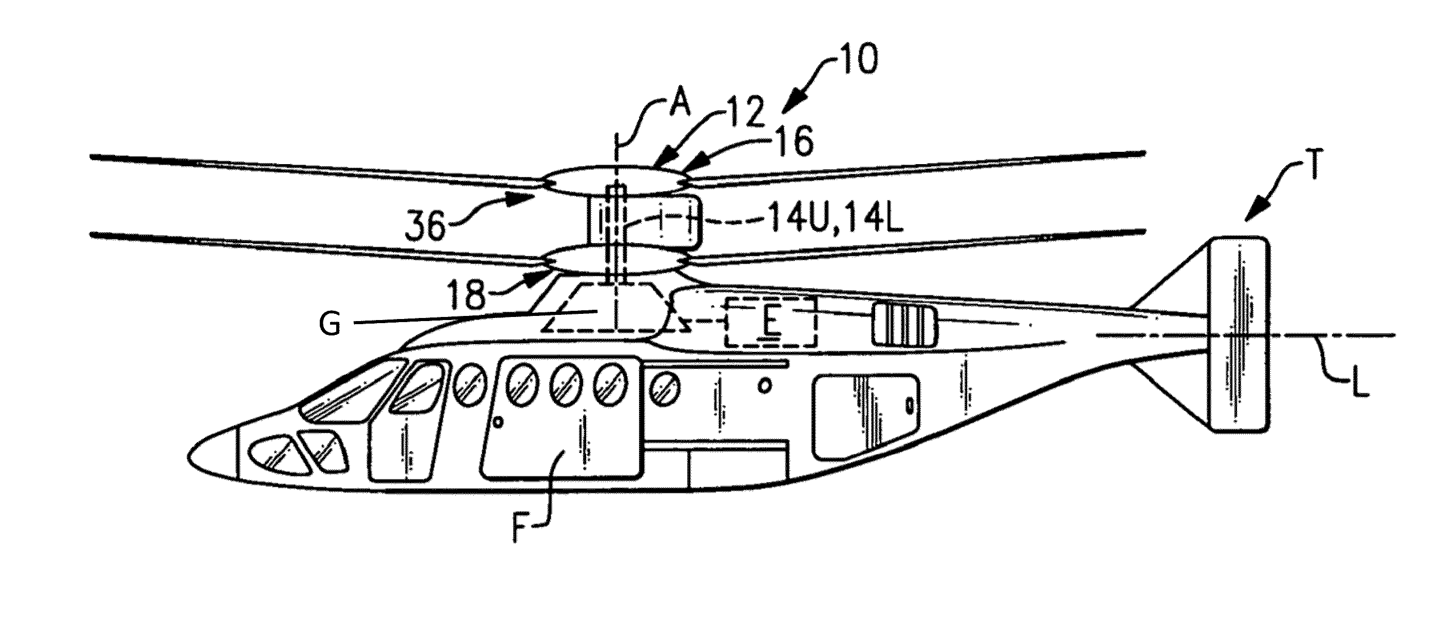
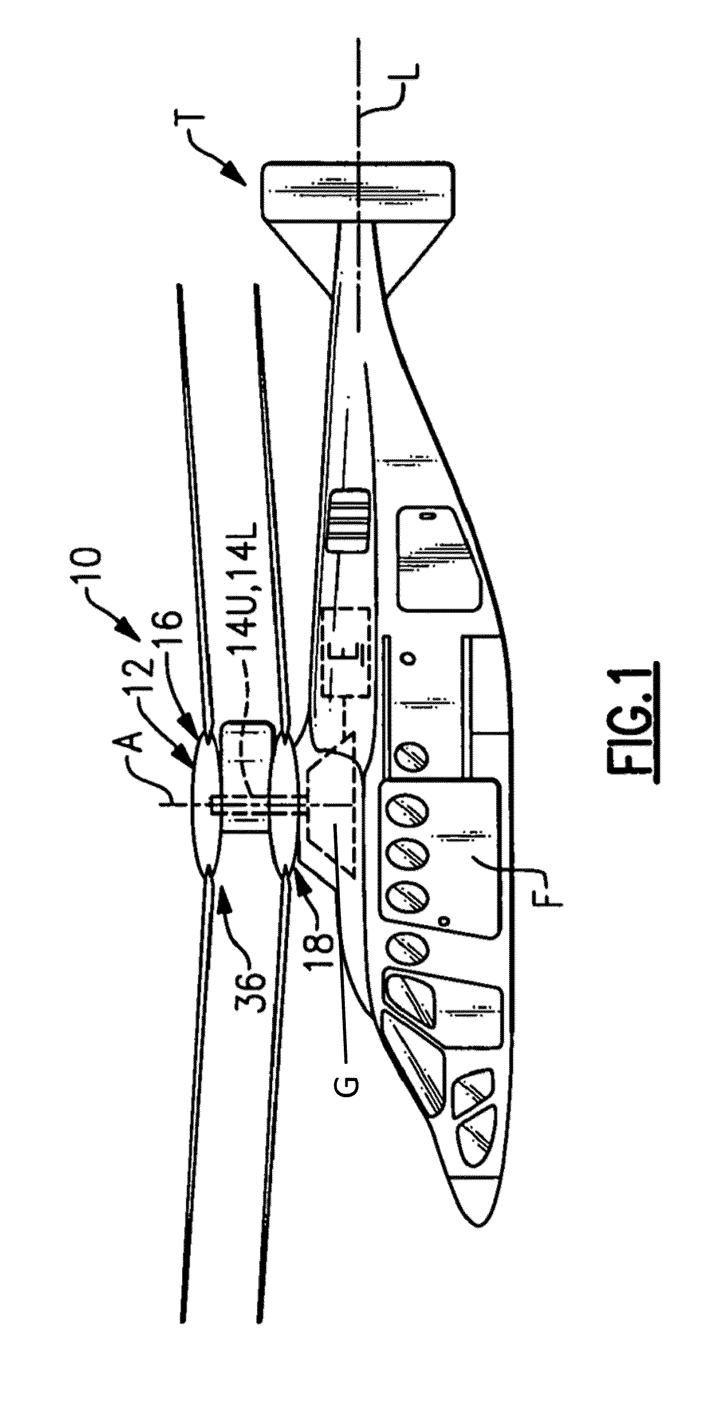
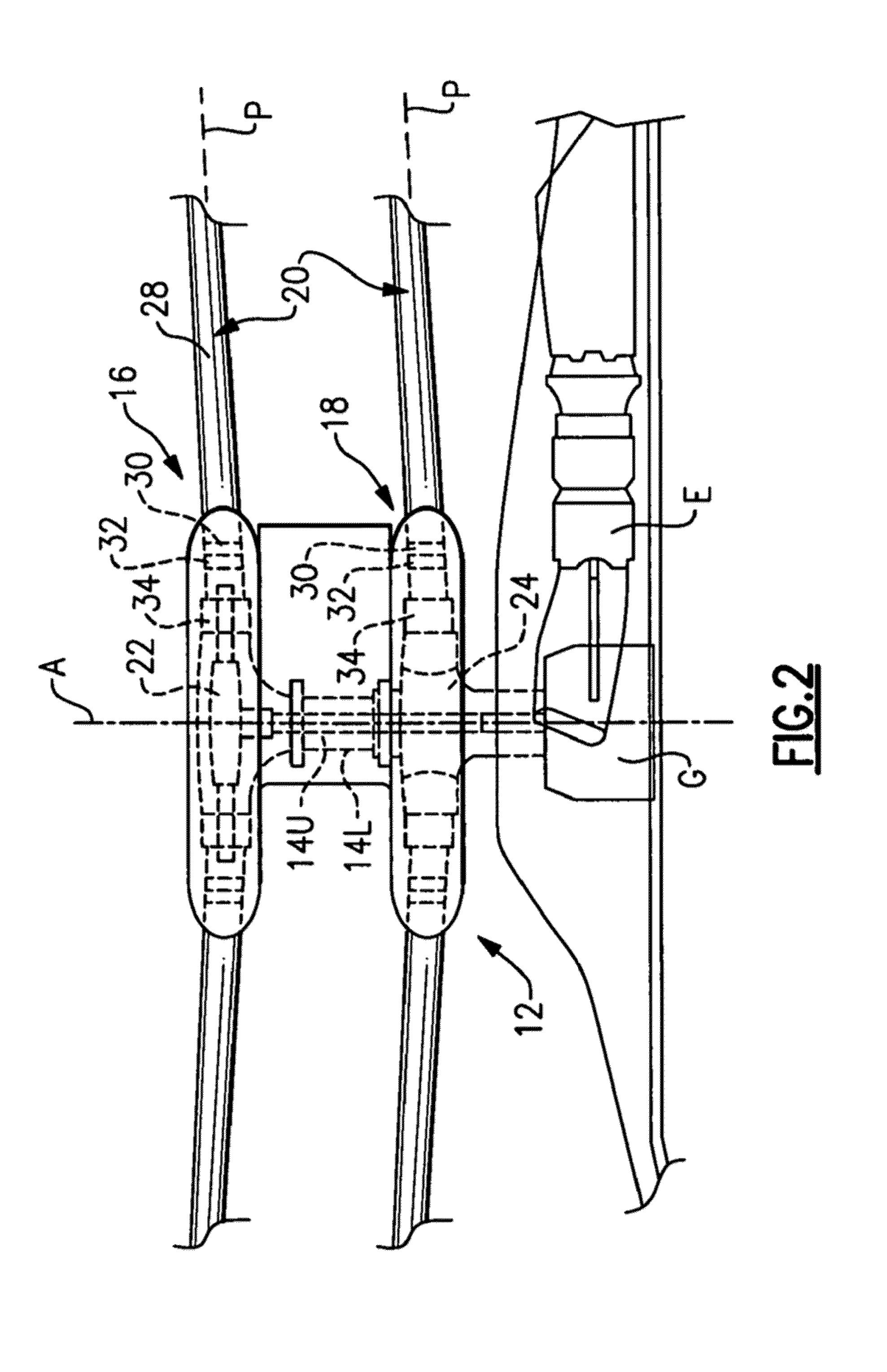
[0018]FIG. 1 illustrates an exemplary vertical takeoff and landing (VTOL) rotary wing aircraft 10 having a dual, counter-rotating main rotor system 12, which rotates about a rotating main rotor shaft 14U, and a counter-rotating main rotor shaft 14L (FIG. 2), both about an axis of rotation A. The aircraft 10 includes an airframe F which supports the dual, counter-rotating, coaxial main rotor system 12 as well as an optional translational thrust system T which provides translational thrust during high speed forward flight, generally parallel to an aircraft longitudinal axis L. Although a particular counter-rotating, coaxial rotor system aircraft configuration is illustrated in the disclosed embodiment, other rotor systems and other aircraft types such as tilt-wing and tilt-rotor aircrafts will also benefit from the present invention.

[0019]A main gearbox G located above the aircraft cabin drives the rotor system 12. The translational thrust system T may be driven by the same main gearb...


PUM


Abstract

A rotary wing aircraft is provided including a dual counter-rotating, coaxial rotor system having an upper rotor system and a lower rotor system rotatable about a common axis. A plurality of blade assemblies is mounted to a portion of either the upper rotor system or the lower rotor system. A plurality of individually controllable actuators is coupled to each of the plurality of blade assemblies. Each of the plurality of actuators is configured to control movement of the coupled blade assembly about a pitch axis. The rotary-wing aircraft additionally includes a sensor system within an airframe. A higher harmonic control (HHC) controller is arranged in communication with the sensor system and the plurality of actuators to individually control the upper rotor system and the lower rotor system to reduce vibration.

Description

BACKGROUND OF THE INVENTION[0001]Exemplary embodiments of the invention generally relate to a rotary wing aircraft, and more particularly, to a higher harmonic vibration control system therefor.[0002]The reduction of vibrations is a primary goal in rotary-wing aircraft design. Such vibrations may contribute to crew fatigue, increased maintenance, and operating costs. A major cause of such vibrations is periodic aerodynamic loads on the rotor blades.[0003]An effective method of reducing rotor-blade induced vibrations is to control the harmonic airload at the source, i.e., on the rotor blades. For an N bladed rotor, harmonic loads at a frequency rate of (N−1) per revolution, N per revolution, and (N+1) per revolution are transmitted to the rotor hub. All three harmonic load frequencies in the rotating rotor frame of reference result in fuselage vibration in the non-rotating frame of reference at the frequency ratio of N / revolution (hereinafter NP). The function of a higher harmonic co...

Claims


Application Information

Patent Timeline
IPC IPC(8): B64C27/12
CPCB64C27/12B64C27/001B64C27/10B64C2027/004B64C2027/7216B64C27/72Y02T50/30B64C2027/7244
Inventor MAYRIDES, BRYAN D.WELSH, WILLIAM A.WEINER, STEVEN D.
Owner SIKORSKY AIRCRAFT CORP
Why Eureka
Try Eureka