Liquid pump using elastomeric piston, piston assembly and manufacturing method thereof

a technology of elastomeric pistons and liquid pumps, which is applied in the direction of liquid fuel engines, positive displacement liquid engines, single-unit apparatuses, etc., can solve the problems of increasing equipment costs, difficulty in manufacturing and assembly, and difficulty in improving product precision, so as to facilitate automatic assembly and improve product precision and quality.

Inactive Publication Date: 2014-10-23
DING YAO WU
View PDF7 Cites 10 Cited by
  • Summary
  • Abstract
  • Description
  • Claims
  • Application Information

AI Technical Summary

Benefits of technology

[0012]In view of the shortcomings of the liquid pumps with an elastomeric piston of the prior art, the main object of this invention is to provide a liquid pump using an elastomeric piston that has improved product precision and quality and facilitates automatic assembly.
[0013]Another object of the invention is to provide a manufacture method of a piston assembly for liquid pumps that facilitates automatic production and is advantageous to ensure product precision and quality.
[0014]Still another object of the invention is to provide a piston assembly for liquid pumps that has improved operation reliability.

Problems solved by technology

However, conventional liquid pumps of this type mostly have problems such as difficulty to manufacture and assembly and difficulty to improve the product precision.
Such a manufacture method, using a complicated composite mould and thus involving multiple procedures such as withdrawing cores and splitting moulds, not only increases the equipment costs but also limits improvement of the productivity.
Moreover, it is well known that the manufacture using half moulds has shortcomings such as low productivity and poor precision, wherein there exist inevitable problems of mould misalignment and flashing production due to the parting surface, which adversely affects the dimension precision of products, and finally, may lead to leakage of a finished assembly.
Another problem with the pump configurations of the prior art lies in that: in the one-piece piston rod / piston engaging portion / piston head, the outer diameter of the piston engaging portion for engaging with the piston is smaller than those of both the piston rod and the piston head, and the former is located between the two latter, thus, during engaging the piston onto the piston engaging portion, it is necessary to forcibly broaden the central hole of the annular inner flange of the piston to a size enough for the piston rod to pass so as to fit the piston onto the piston engaging portion.
Such a fitting way is time- and labor-consuming, and is not suitable for an automatic assembly line.
Moreover, in the course that the piston rod or piston head with a big diameter is inserted through the small central hole of the annular inner flange of the piston, the inner circumference of the hole is prone to be damaged, thereby adversely affecting the operation life of the piston assembly and thus of the liquid pump.
However, the upper portion 2135 of the piston 213 is rather thick and thus is not easy to deform, which may result in that the transverse passage 216 cannot be opened or can be opened but not in time, thereby causing the pump to be unable to operate normally.

Method used


Image

  • Liquid pump using elastomeric piston, piston assembly and manufacturing method thereof
  • Liquid pump using elastomeric piston, piston assembly and manufacturing method thereof
  • Liquid pump using elastomeric piston, piston assembly and manufacturing method thereof

Examples


Embodiment Construction

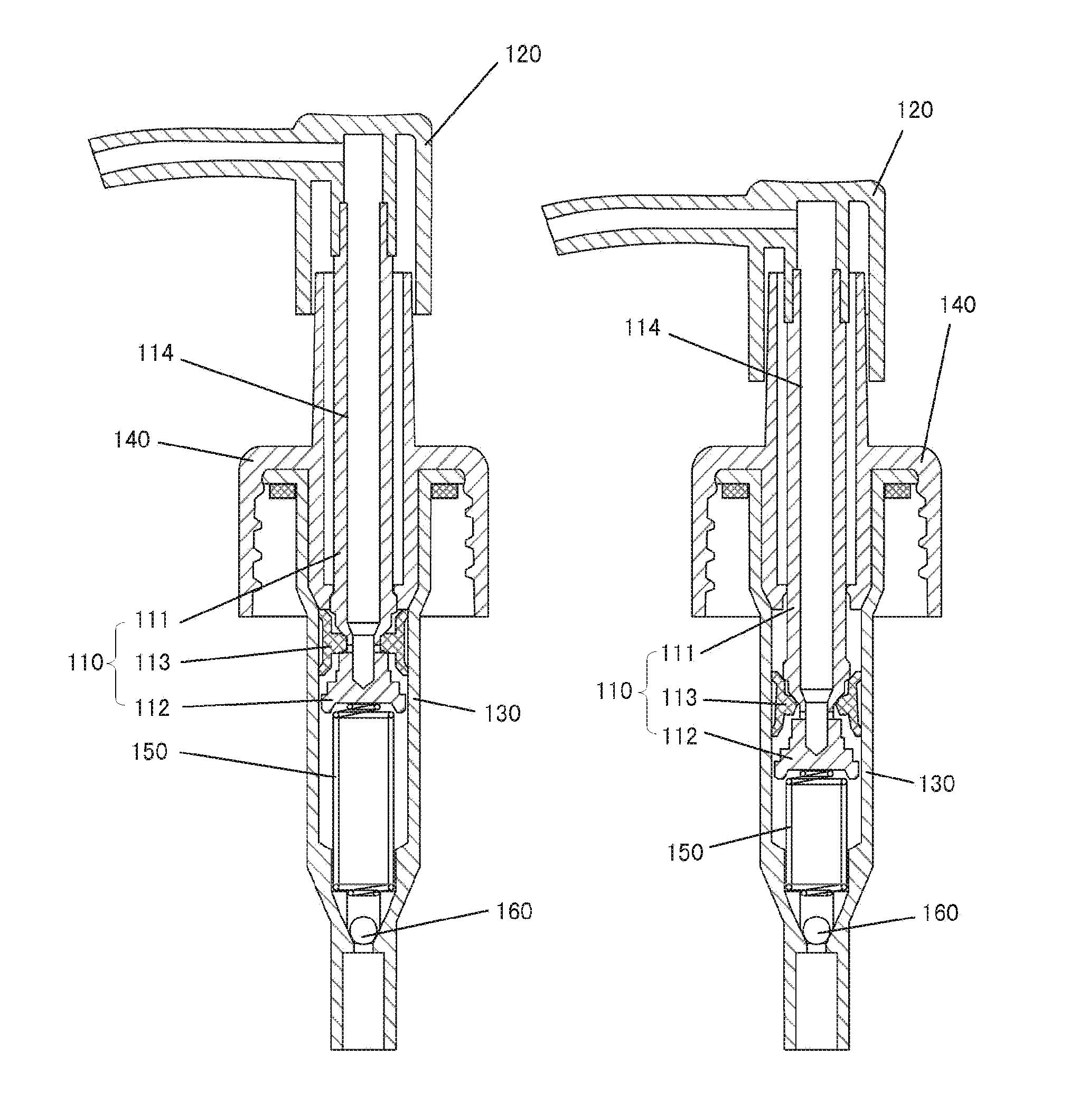
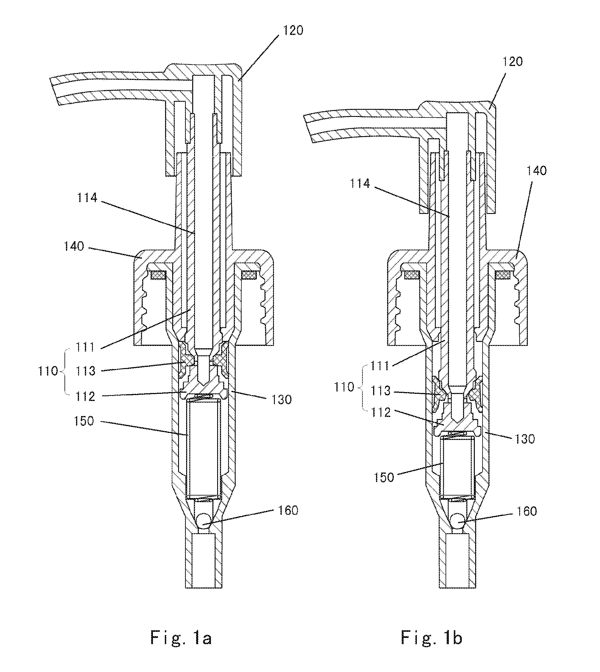
[0059]Referring to FIGS. 3-6, a liquid pump of the invention mainly comprises a piston assembly 10, a press head 20, a cylinder 30, an integrated threaded sleeve-cylinder cap 40, a spring 50 and a lower non-return ball valve 60. The liquid pump can, through its integrated threaded sleeve-cylinder cap 40, be mounted at an opening (usually an open neck) of a container (not shown) of a liquid product. Of course, the threaded sleeve and cylinder cap can also be of the separate type. As the invention focuses on the piston assembly of liquid pump, other components of the liquid pump, which may be of the conventional structures, are not described in detail in this application.

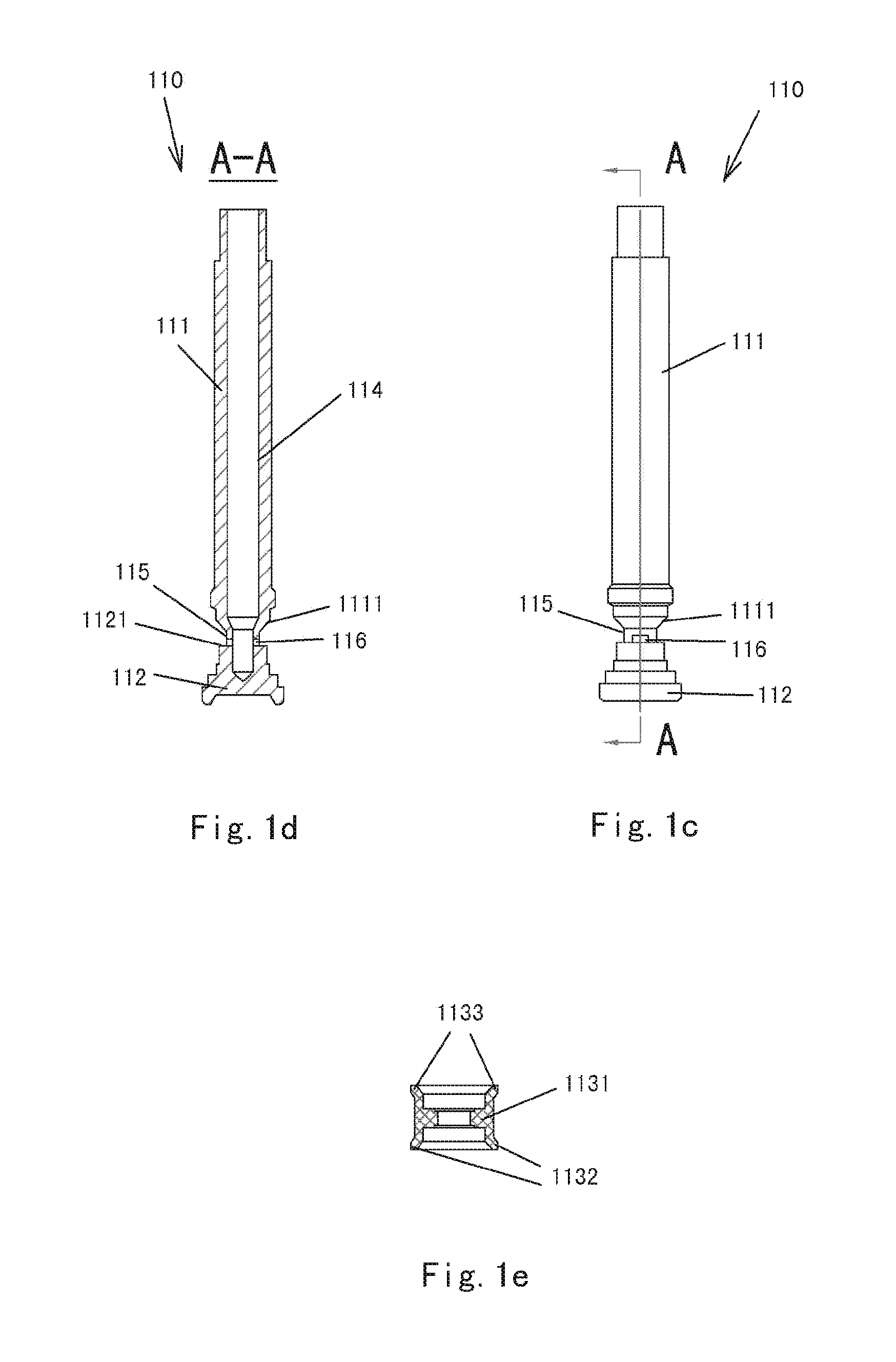
[0060]The piston assembly 10 is composed of a piston rod 11, a piston head 12 and a piston 13 fitted around a piston engaging portion 15 between the piston rod 11 and the piston head 12. Both the piston rod 11 and the piston head 12 can be made of a relatively rigid plastic material, for example, polypropylene, and th...


PUM

PropertyMeasurementUnit
longitudinal lengthaaaaaaaaaa
diameteraaaaaaaaaa
pressuresaaaaaaaaaa

Abstract

The invention provides a liquid pump using an elastomeric piston. The liquid pump has a piston assembly (10), which comprises: a piston rod (11); a piston head (12); a piston engaging portion (15) which is between the piston rod and the piston head in a necking shape; and a piston (13) made of an elastomeric material and sleeved around the piston engaging portion between the piston rod and piston head. The piston rod and piston head are formed separately and then assembled together. The piston engaging portion (15) is composed of a piston-engaging-portion formation part of at least one of the piston rod and the piston head. The invention also provides a method of manufacturing the piston assembly (10). The invention further provides a piston assembly (10) for a liquid pump. The piston assembly has a piston (13) which is provided with an annular notch (133) formed on the periphery of an upper end of the piston (13) where an annular inner flange (131) is formed. The piston assembly and its manufacture method are helpful to improving product precision and quality and facilitate automated assembly, and are specially used for the liquid pumps using an elastomeric piston.

Description

FIELD OF THE INVENTION[0001]This invention relates generally to a liquid pump, and particularly to a liquid pump which incorporates an elastomeric piston.BACKGROUND OF THE INVENTION[0002]A liquid pump is generally mounted at an opening of a container filled with an oil-like liquid, and used for dispensing the liquid out of the container by its user's manual press operation. Liquid pumps of this type commonly incorporate a piston made of an elastomeric material (such as Nitrile Butadiene Rubber (NBR)) but not of a plastic material, because the elastomeric materials are less susceptible to the oil-like liquids than the plastic materials which may generate deformation under the action of the oil-like liquids.[0003]At present, there are various liquid pumps of the above type that incorporate an elastomeric piston and are specially used for dispensing oil-like liquid products. However, conventional liquid pumps of this type mostly have problems such as difficulty to manufacture and assem...

Claims


Application Information

Patent Timeline
Patent Type & Authority Applications(United States)
IPC IPC(8): F04B39/00
CPCF04B39/0011F04B53/14F04B53/22Y10T29/49249B05B11/1026B05B11/1023B05B11/1047B05B11/1059B05B11/1077
Inventor DING, YAO WU
Owner DING YAO WU
Why Eureka
Try Eureka