Method and system for producing a synthesis gas using an oxygen transport membrane based reforming system with secondary reforming

a technology of oxygen transport membrane and synthesis gas, which is applied in the direction of oxygen/ozone/oxide/hydroxide, chemical/physical/physico-chemical processes, organic chemistry, etc., can solve the problems of excessive carbon formation, complex installation, and high cost of conventional methods of producing a synthesis gas such as the one discussed abov

Active Publication Date: 2014-10-30
PRAXAIR TECH INC
View PDF3 Cites 39 Cited by
  • Summary
  • Abstract
  • Description
  • Claims
  • Application Information

AI Technical Summary

Benefits of technology

[0039]While the present invention has been characterized in various ways and described in relation to preferred embodiments, as will occur to those skilled in the art, numerous, additions, changes and modifications thereto can be made without departing from the spirit and scope of the present invention as set forth in the appended claims.

Problems solved by technology

However, both the ATR as well as POx processes require separate air separation units (ASU) to produce high-pressure oxygen, which adds complexity as well as capital and operating cost to the overall process.
As can be appreciated, the conventional methods of producing a synthesis gas such as have been discussed above are expensive and require complex installations.
There is an operational problem with all of these oxygen transport membrane based systems because such oxygen transport membranes need to operate at high temperatures of around 900° C. to 1100° C. Where hydrocarbons such as methane and higher order hydrocarbons are subjected to such high temperatures within the oxygen transport membrane, excessive carbon formation occurs, especially at high pressures and low steam to carbon ratios.
The carbon formation problems are particularly severe in the above-identified prior art oxygen transport membrane based systems.
Other problems that arise with the prior art oxygen transport membrane based reforming systems are the cost of the oxygen transport membrane modules and the lower than desired durability, reliability and operating availability of such oxygen transport membrane based reforming systems.
These problems are the primary reasons that oxygen transport membranes based reforming systems have not been successfully commercialized.

Method used


Image

  • Method and system for producing a synthesis gas using an oxygen transport membrane based reforming system with secondary reforming
  • Method and system for producing a synthesis gas using an oxygen transport membrane based reforming system with secondary reforming

Examples


Embodiment Construction

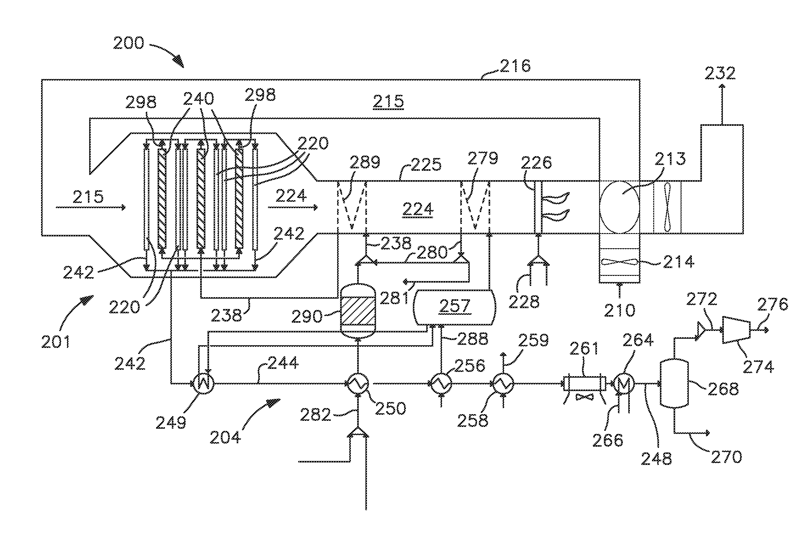
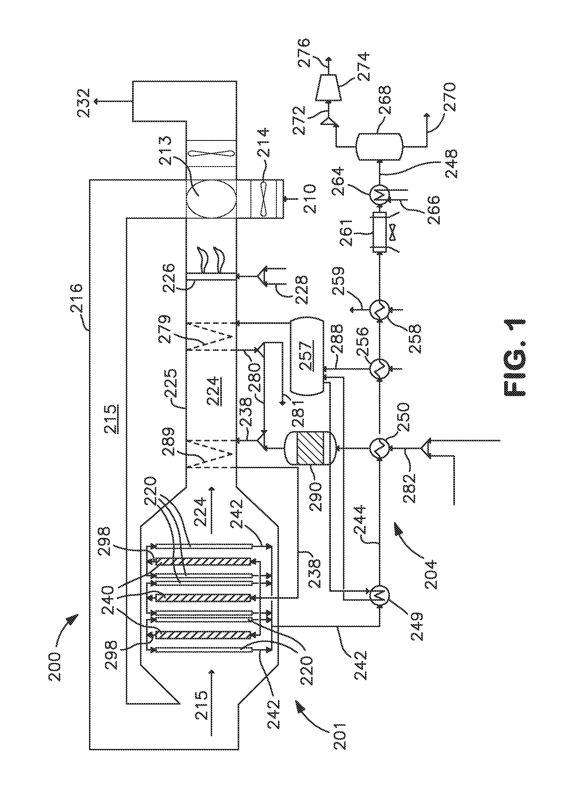
[0018]FIG. 1 provides a schematic illustration of an embodiment of an oxygen transport membrane based reforming system 201 and assembly 200 in accordance with the present invention. As seen therein, an oxygen containing stream 210, such as air, is introduced to the system by means of a forced draft (FD) fan 214 into a heat exchanger 213 for purposes of preheating the oxygen containing feed stream 210. Heat exchanger 213 is preferably a high efficiency, cyclic continuously rotating ceramic regenerator disposed in operative association with the oxygen containing feed stream 210 and the heated retentate stream 224. The ceramic regenerator 213 which heats the incoming air feed stream 210 to a temperature in the range of about 500° C. to 1050° C.

[0019]The oxygen depleted air leaves the oxygen transport membrane reforming tubes as a heated retentate stream 224 at the same or slightly higher temperature than the heated air feed stream 215. Any temperature increase, typically 224 is first u...


PUM

PropertyMeasurementUnit
temperatureaaaaaaaaaa

Abstract

A method and system for producing a synthesis gas in an oxygen transport membrane based reforming system is disclosed that carries out a primary reforming process, a secondary reforming process.

Description

CROSS REFERENCE TO RELATED APPLICATIONS[0001]This application claims priority to and the benefit of U.S. provisional patent application Ser. No. 61 / 816,326 filed on Apr. 26, 2012, the disclosure of which is incorporated by reference herein.FIELD OF THE INVENTION[0002]The present invention relates to a method and system for producing a synthesis gas in an oxygen transport membrane based reforming system, and more particularly, a method and system for producing a synthesis gas with very low methane slip in an oxygen transport membrane based reforming system that provides both primary and secondary reforming.BACKGROUND[0003]Synthesis gas containing hydrogen and carbon monoxide is produced for a variety of industrial applications, for example, the production of hydrogen, chemicals and synthetic fuel production. Conventionally, the synthesis gas is produced in a fired reformer in which natural gas and steam is reformed in nickel catalyst containing reformer tubes at high temperatures (e....

Claims


Application Information

Patent Timeline
Patent Type & Authority Applications(United States)
IPC IPC(8): C01B3/26
CPCC01B3/26C01B3/38C01B13/0251C01B2203/1235C01B2203/0227C01B3/382C01B3/384C01B2203/0233C01B2203/0244C01B2203/0261C01B2203/04C01B2203/0495C01B2203/0838C01B2203/0883C01B2203/1205C01B2203/127C01B2203/142C01B2203/80B01J8/0496B01J8/009B01J8/0457B01J2208/0053B01J2219/00006B01J19/24C01B13/02B01J19/2475B01J2219/00051B01J2219/00157B01J2219/24C01B3/386
Inventor CHAKRAVARTI, SHRIKARDMEVICH, RAYMOND FRANCISSHAH, MINISH M.STUCKERT, INES C.
Owner PRAXAIR TECH INC
Why Eureka
Try Eureka